Epson MX-80II F/T User Manual
Epson MX-80II F/T Manual
 |
View all Epson MX-80II F/T manuals
Add to My Manuals
Save this manual to your list of manuals |
Epson MX-80II F/T manual content summary:
- Epson MX-80II F/T | User Manual - Page 1
MX-80 EPSON DOT MATRIX PRINTER TYPE II Operation Manual EPSON P8190014-2 - Epson MX-80II F/T | User Manual - Page 2
paper 13 6.3. Column layout on fanfold paper 14 6.4. Top of form position setting 14 7. Gap Adjustment 15 8. Power Connection 15 INSTALLATION OF MX-80 F/T TYPE II 17 1. Unpacking 17 1.1. Unpacking steps 17 1.2. Repacking steps 17 2. Counting the Parts 17 3. Installation of the Printer 18 - Epson MX-80II F/T | User Manual - Page 3
Setting of DIP switch No. 1 4 5 5.2. Setting of DIP switch N O. 2 46 5.3. Coding tables 47 5.4. Setting sequence of functional specifications 4 8 WHAT IS THE MX-80 TYPE II 52 1. What Is a Dot Matrix Printer 52 2. Definitions of Some Terms Often Used 54 3. Control Codes in the Text Mode 56 - Epson MX-80II F/T | User Manual - Page 4
LIST OF FIGURES Fig. 1 EPSON MX-80 Type II and MX-80 F/T Type II Dot Matrix Printers ... 1 Fig. 2 Contents of Carton 4 Fig. 3 Laying Printer on Firm Surface 5 Fig. 4 Assembly Tools 6 Fig. 5 Paper (3 30 Fig. 39 Loading of Cut Paper Sheet 31 Fig. 40 Adjustment of Inserted Paper Position 31 -iii- - Epson MX-80II F/T | User Manual - Page 5
and Indicators on Control Panel 36 Fig. 48 Printer Initial Check 38 Fig. 49 Flowchart of Paper Out Status Release Procedure 39 Fig. 50 Removing Manual Paper Feed Knob 41 Fig. 51 Loosening All 4 Screws 41 Fig. 52 Pulling Out Wires Hooked to Control Panel 42 Fig. 53 Construction of Type - Epson MX-80II F/T | User Manual - Page 6
LIST OF TABLES T a b l e 1 I n t e r f a c e S i g n a l s i n P a p e r - O u t S t a t u s 39 Table 2 Functions and Conditions of DIP Switch No. 1 4 5 Table 3 Character Size and Maximum Column Length 4 6 Table 4 Functions and Conditions of DIP Switch No. 2 46 Table 5 International Character - Epson MX-80II F/T | User Manual - Page 7
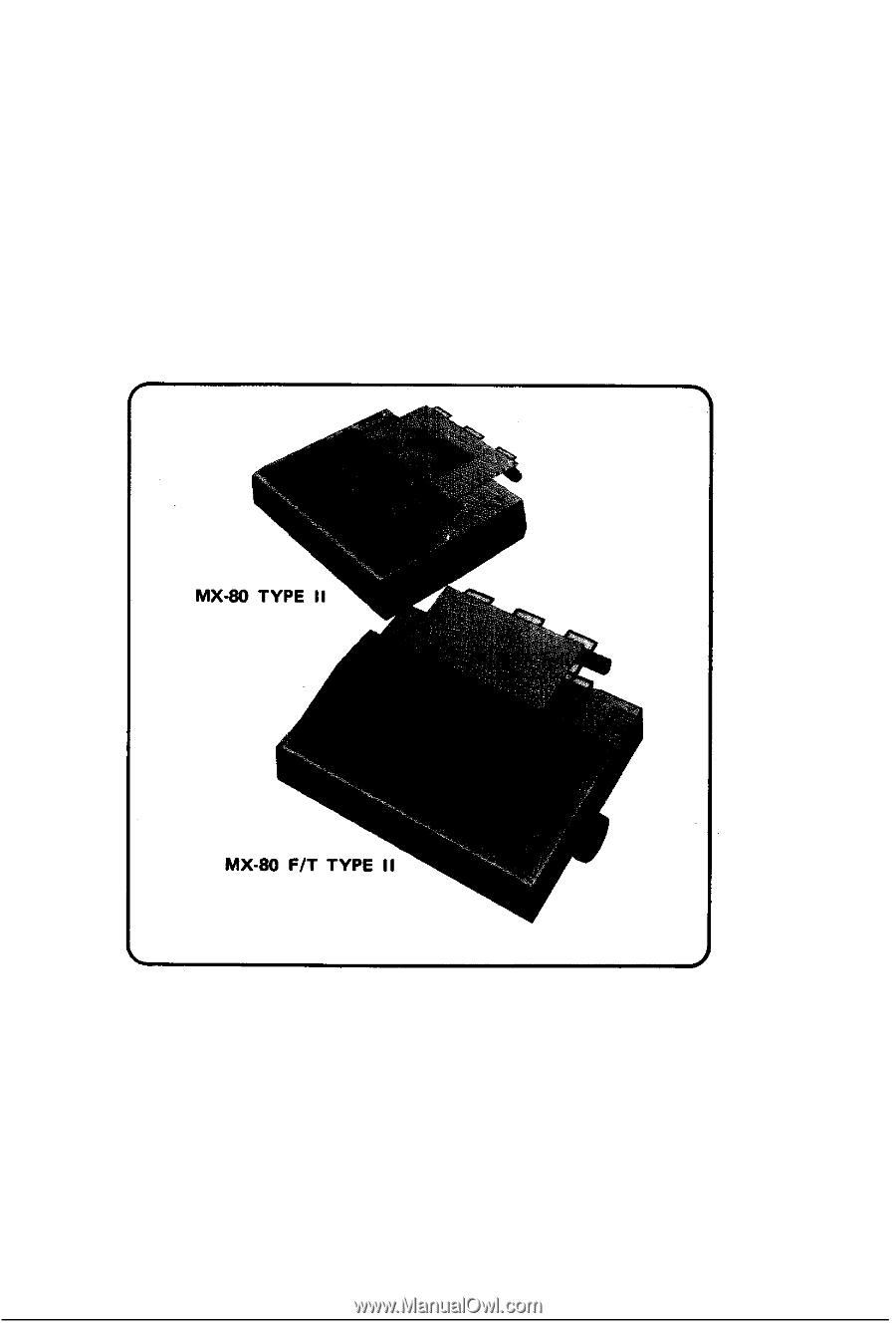
and adjustable sprocket feed type called "MX-80 F/T Type II" is also available. In this manual, installation of MX-80 Type II and MX-80 F/T Type II will be described dot wires respectively u n d e r s o f t w a r e control. Fig. 1 EPSON MX-80 Type I I and MX-80 F/T Type I I Dot Matrix Printers -1- - Epson MX-80II F/T | User Manual - Page 8
2. Characteristics The MX-80 Type II and MX-80 F/T Type II have been designed as a printer with versatile functions characters/line (enlarged character) (b) 66 characters/line (enlarged-condensed character) (c) 80 characters/line (normal character) (d) 132 characters/line (condensed character) (e) - Epson MX-80II F/T | User Manual - Page 9
1. Open the carton. STEP 2. Remove accessories. STEP 3. Remove the MX-80 Type I I holding its underside and lifting it straight up with the be saved for reuse in case the MX-80 Type II requires reshipment in the future. 2. Counting the Parts The MX-80 Type II and standard accessories are as - Epson MX-80II F/T | User Manual - Page 10
1. MX-80 Type I I Dot Matrix Printer 1 2. Separator 1 3. Cartridge Ribbon 1 4. Power Cord (Only European Type 220/240V) 1 5. MX-80 Type I I Operation Manual 1 Fig. 2 Contents of Carton -4- - Epson MX-80II F/T | User Manual - Page 11
3. Installation of the Printer (1) Operating site selection When installing the MX-80 Type I I, observe the following instructions. (a) Place the Printer on a bench, tabletop or any other convenient flat surface with enough room for the separator in the back of the Printer. Your - Epson MX-80II F/T | User Manual - Page 12
with a protective paper inserted between the inner and outer paper guides to protect the paper end detector from damage due to shocks or vibrations during transportation. Before using the Printer, be sure to remove this paper. If the MX-80 Type II is to be reshipped, remember to return it to - Epson MX-80II F/T | User Manual - Page 13
Right Side of the Printer Fig. 5 Removal of Shipping Screws NOTE: Save the two shipping screws for possible future use. < SUPPLEMENT > l If the printer lid is an obstacle when removing the shipping screws, be sure to take off the printer lid by observing the following steps. Rough or careless - Epson MX-80II F/T | User Manual - Page 14
the left side of the printer lid onto the left projection and push the printer lid down, Fig. 7 Remounting of Printer Lid 4. Cartridge Ribbon Setting EPSON's Cartridge Ribbon is compact, long-lasting, and very easy to set and remove. Furthermore, you have no need to soil your fingers in handling it - Epson MX-80II F/T | User Manual - Page 15
STEP 4. Put the ribbon between the head nose and the ribbon mask. In this case, the ribbon can be set easily by hooking it to the edge of the head nose and turning the ribbon feeding knob of the cartridge case in the direction of the arrow (i.e., counterclockwise) while depressing the ribbon with a - Epson MX-80II F/T | User Manual - Page 16
.) Fig. 11 Separator Installation 6. Paper Loading 6.1. Loading of fanfold paper The MX-80 Type II Printer accommodates fanfold paper from 4" to 10" in width. To detach it from the platen. STEP 3. Confirm that the paper guide roller is at the center of the sprocket shaft. If not, set it at - Epson MX-80II F/T | User Manual - Page 17
of Fanfold Paper STEP 5. STEP 6. Push the paper into the insertion slot between the paper guides at the rear part of the printer mechanism. NOTE: Be sure to pass the paper beneath the upper paper guide. After the leading edge of the paper has emerged from the Printer, pull it out gently - Epson MX-80II F/T | User Manual - Page 18
STEP 7. Raise the two sprocket lock levers to loosen, and adjust the sprocket pin position to the paper width. (See Fig. 13.) Fig. 13 Raising of Sprocket Lock Levers STEP 8. Engage the paper feed holes of the paper on the feeding pins, push the scale back into position, and adjust the tension of - Epson MX-80II F/T | User Manual - Page 19
lid on the Printer. Fig. 15 Printer with Fanfold Paper Set Completely NOTE: When the MX-80 Type II is to be used on a desk or a bench, arrangement of the fanfold paper in parallel with the MX-80 Type II as shown below will permit the paper to be folded in an accordion style - Epson MX-80II F/T | User Manual - Page 20
width is supplied with the MX-80 Type I I, the graduations on the scale can be used as the indexes of print column positions (1 to 80). Alignment of the print then align this mark with the matchmarks on the sprockets by turning the manual paper feed knob. At this point, turn the Power Switch on and - Epson MX-80II F/T | User Manual - Page 21
paper sheets is used, be sure that no characters are printed within the area two lines each above and below the perforation. 8. Power Connection The EPSON MX-80 Type II Dot Matrix Printer is capable of operating on the following three types of AC power. (1) 115V AC, 60Hz (2) 220V AC, 50Hz (3) 240V - Epson MX-80II F/T | User Manual - Page 22
-16- - Epson MX-80II F/T | User Manual - Page 23
, notify the carrier immediately. 1.1. Unpacking steps Unpacking steps are as follows: STEP 1. Open the carton. STEP 2. Remove accessories. STEP 3. Remove the MX-80 F/T Type I I by holding its underside and lifting it straight up with the packing material attached. STEP 4. Place the Printer with the - Epson MX-80II F/T | User Manual - Page 24
4. Power Cord (Only European Type 220/24OV) 1 5. MX-80 F/T Type I I Operation Manual 1 Fig. 19 Contents of Carton 3. Installation of the Printer (1) Operating site selection When installing the MX-80 F/T Type I I, observe the following instructions. (a) Place the Printer on a bench, tabletop or - Epson MX-80II F/T | User Manual - Page 25
. 20 Laying Printer on Firm Surface (2) Removal of protective paper for paper end detector The MX-80 F/T Type II is provided with a protective paper inserted between the inner and outer paper guides to protect the paper end detector from damage due to shocks or vibrations during transportation - Epson MX-80II F/T | User Manual - Page 26
Type I I against any damage that may be caused by shocks or vibrations during transportation. Therefore, before operating the MX-80 F/T Type II, remove the screws as described below. (See Fig. 22.1 STEP 1. Stand the printer on its left side. STEP 2. Remove with a screwdriver, the two - Epson MX-80II F/T | User Manual - Page 27
STEP 1. STEP 2. Stand the printer lid upright. Push the printer lid toward the right and pull up its left side. (See Figs 23 (1) and (2).) NOTE: The printer lid shown in Fig. 23 (2) is an Optional accessory. -21- - Epson MX-80II F/T | User Manual - Page 28
4. Cartridge Ribbon Setting EPSON's Cartridge Ribbon is compact, long-lasting, and very easy to set and remove. Furthermore, you have no need to soil your fingers in handling it. - Epson MX-80II F/T | User Manual - Page 29
NOTES: 1. Incorrect setting of the ribbon may cause it to come off. (See Fig. 26.) 2. Confirm that the ribbon is neither twisted nor creased and that the cartridge is set properly. Fig. 26 Examples of Correct and Incorrect Ribbon Setting 5. Separator Installation The separator of the Printer - Epson MX-80II F/T | User Manual - Page 30
6. Dismounting of Tractor Unit The tractor unit of the MX-80 F/T Type I I is detachable. If it is an obstacle when using roll paper, it can be taken out as follows; STEP 1. Release the lock levers of - Epson MX-80II F/T | User Manual - Page 31
7. Paper Loading 7.1. Fanfold paper 7.1.1. Loading of fanfold paper The MX-80 F/T Type I I Printer accommodates fanfold paper from 4" to 10" Printer to detach the scale from the platen. STEP 4. Confirm that the paper guide roller is at the center of the sprocket shaft. If not, set it at the center - Epson MX-80II F/T | User Manual - Page 32
STEP 8. Raise the two sprocket lock levers to loosen, and adjust the sprocket pin position to the paper width. (See Fig. 31.) STEP 6. Engage the paper feed holes of the paper on the feeding pins, push the scale back into position, and adjust the tension of the paper. Then push the paper holding - Epson MX-80II F/T | User Manual - Page 33
STEP 10. Put the printer lid on the Printer. (See Fig. 33.) NOTE: When the MX-80 F/T Type I I is to be used on a desk or a bench, arrangement of the fanfold paper in parallel with the MX-80 F/T Type II as shown below will permit the paper to be folded in an accordion style. 7.1.2. Removal of - Epson MX-80II F/T | User Manual - Page 34
is supplied with the MX-80 F/T Type II, the graduations on the scale can be used as the indexes of print column positions (1 to 80). Alignment of the the power switch is turned on. Namely, adjust the paper position by the manual paper feed knob S O that the required line position (i.e., the point at - Epson MX-80II F/T | User Manual - Page 35
7.2. Roll paper 7.2.1. Roll paper holder EPSON offers the roll paper holder as an optional accessory for the MX-80 F/T Type II. See Appendix 7 for the assembly instructions on Roll Paper Holder. 7.2.2. Loading of roll paper The MX-80 F/T Type II accommodates a roll of single ply paper measuring 8.5 - Epson MX-80II F/T | User Manual - Page 36
7.3. Cut paper sheet 7.3.1. Loading of cut paper sheet The MX-80 F/T Type I I accommodates cut paper sheets measuring 8.3" to 8.5" in width. To from the platen. (See Fig. 39.) STEP 4. Confirm that the paper guide roller is at the center of the sprocket shaft. If not, set it at the center of the - Epson MX-80II F/T | User Manual - Page 37
STEP 6. STEP 7. Lock the release lever. While turning the manual paper feed knob clockwise, confirm that the paper advances straight up. (See Fig. 40.) Fig. 40 Adjustment of Inserted Paper Position If not, adjust the - Epson MX-80II F/T | User Manual - Page 38
b) If the cut paper sheet or form is not long enough to align the side edges, align the top edge of the paper with the form position setting mark on the tractor unit. (See Fig. 42.) Fig. 42 Form Position Setting Mark The print area on the cut paper sheet (when printing it with the tractor unit - Epson MX-80II F/T | User Manual - Page 39
Fig. 44 Setting of Cut Paper Sheet STEP 8. NOTES: 1. The Paper End Detector function may be disabled under software control (ESC 8; refer to page 66) provided printing is left off within 7.5 mm from the paper bottom edge. 2. If the paper is set on the line marked l/4 as shown in Fig. 44, then the - Epson MX-80II F/T | User Manual - Page 40
sheets is used, be sure that no characters are printed within the area two lines each above and below the perforation. 9. Power Connection The EPSON MX-80 F/T Type I I Dot Matrix Printer is capable of operating on the following three types of AC power. (1) 115V AC, 60Hz (2) 220V AC, 50Hz (3) 240V - Epson MX-80II F/T | User Manual - Page 41
-35- - Epson MX-80II F/T | User Manual - Page 42
OPERATION 1. Switches and Indicators There are three switches and four indicators (green LED's) on the control panel and one power switch on the right side of the Printer case. In this section, panel operating procedures are covered in sufficient detail for the user to become familiar with the - Epson MX-80II F/T | User Manual - Page 43
FF SW: (Form Feed) LF SW: (Line Feed) When this switch is depressed once, the paper is advanced vertically to the next Top of Form position. This switch must be depressed while the Printer is OFF-LINE. Otherwise, the form feed operation will not be carried out. The Top of Form position is - Epson MX-80II F/T | User Manual - Page 44
1.3. Printer initial check Take the following steps and become familiar with the Printer. -38- - Epson MX-80II F/T | User Manual - Page 45
code (H). (See page 66 for the BE L code.) 3. Paper End Detector (1) When the paper end detector (a reed switch located on the paper guide) detects that the paper is nearly exhausted, the signals on the interface connector change to the following status, and the printing operation stops. Table - Epson MX-80II F/T | User Manual - Page 46
become invalid hardwarewise. (b) Enter control code "ESC 8" and the paper end detecting function will become invalid softwarewise. 4. Self -Test The MX-80 Type I I has a self-test (self-diagnostic) function to check the following. (1) Print head operation and printing quality (2) Operation of the - Epson MX-80II F/T | User Manual - Page 47
static electricity which might be charged in your body, or it may cause damages to internal electronic parts such as LSl's, IC's, etc. Remove the manual paper feed knob (black knob on the right side) by pulling it straight out, with firm but steady pressure. (See Fig. 50.) I Fig. 50 Removing - Epson MX-80II F/T | User Manual - Page 48
Tip the printer right side up again. Gently loosen the upper case. Lift up the cover from the left side. And then pull out the wires hooked to the control panel on the right. (See Fig. 52.) Fig. 52 Pulling Out Wires Hooked to Control Panel -42- - Epson MX-80II F/T | User Manual - Page 49
See the inside of the printer before you set the switches. The printer consists of a printer mechanism, a controller, a transformer and filter circuit board, and a control panel. (See Fig. 53.) -43- - Epson MX-80II F/T | User Manual - Page 50
Position the printer as shown in Fig. 53. There are two "DIP" (DUAL IN-LINE PACKAGE) switches in the HMTP board. (See Fig. 54.) The switches set to the left are ON . . . to the right are OFF. (See Fig. 55.) Each switch No. of the DIP switch functions as described below. So set these switches to suit - Epson MX-80II F/T | User Manual - Page 51
5.1. Setting of DIP Switch No. 1 The DIP switch No. 1 consists of the following 8 pins. A summary of the functions of the respective DIP switch pins and their preset conditions at the time of shipment are shown in Table 2. Table 2 Functions and Conditions of DIP Switch No. 1 (1) SW1-1: Setting this - Epson MX-80II F/T | User Manual - Page 52
. (2) SW2-3: This pin is used to fix AUTO FEED XT signal internally. (Refer to the explanation of control code "CR" in paragraph 3.1 (1) "WHAT IS THE MX-80 TYPE II?".) This signal line is wired ORed with the pin No. 14 of the interface connector. Therefore, to control the pin No. 14 externally - Epson MX-80II F/T | User Manual - Page 53
5.3. Coding tables Appendix 3 shows all available codes when the Printer is set for operation with standard coding by setting the DIP switch pins l-7, 2-l and 2-2 all to ON position. Table 5 shows International Character Set Designation according to the combination of the DIP switch setting. Table 5 - Epson MX-80II F/T | User Manual - Page 54
5.4. Setting sequence of functional specifications The MX-80 Type I I has a choice of various functional specifications such as amount of line spacing, form length per page, number of columns per line, automatic skip-over - Epson MX-80II F/T | User Manual - Page 55
Fig. 57 Setting Form Length per Page -49- - Epson MX-80II F/T | User Manual - Page 56
Fig. 58 Setting Number of Columns per Line -50- - Epson MX-80II F/T | User Manual - Page 57
Fig. 59 Setting Skip-over Perforation Function -51- - Epson MX-80II F/T | User Manual - Page 58
be classified by categories such as impact or non-impact printing method, line or serial printing method and so on. •Broadly speaking, the EPSON MX-80 Type I I belongs to the following categories. Impact printer l Dot Matrix printer •l Serial printer with one line buffer Receive only printer (This - Epson MX-80II F/T | User Manual - Page 59
9 needles vertically and can create distinctive characters like with typewriter. In that sense it is one of the key features that the printer has. EPSON's MX-80 Type II can control each needle programmably, expanding the ability of the printer. See next how the print head works and forms a character - Epson MX-80II F/T | User Manual - Page 60
have a switch or lever to change the line spacing (1/6" or 1/8"). The MX-80 Type II also can do this by DIP switch setting, of course. In bit image mode. On the other hand, with 1/6" line spacing, there is no problem even if upper case characters and lower case ones are mixed in a message. In - Epson MX-80II F/T | User Manual - Page 61
be programmed to acknowledge the code used in computer systems. The MX-80 Type II has 96 character set and control codes. In (2) Escape codes In a lot of control codes that the MX-80 Type II has, you might be confused by the word " codes used in the MX-80 Type I I should not be confused with the - Epson MX-80II F/T | User Manual - Page 62
images in dot configurations. The Text Mode is described in this section while the Bit Image Mode is covered in the following section. The MX-80 Type I I has been designed as a terminal unit capable of various software controls. When control codes are transferred to the Printer, respective functions - Epson MX-80II F/T | User Manual - Page 63
the execution of printing by the CR code. NOTES: 1. When 80 columns of print data (including spaces) are continuously received and the FEED XT is at "LOW" level, only paper feeding is performed. 3. When all 80 columns of data are "SPACE," the carriage assembly does not operate. Under this condition - Epson MX-80II F/T | User Manual - Page 64
tab stops per line are recognized in the Printer, and subsequent tab stops are ignored. The tab stop positions can be specified up to 80 columns in normal character mode and 1 3 2 columns in condensed character mode. The excess tab positions, if specified, will be ignored. in normal character mode - Epson MX-80II F/T | User Manual - Page 65
(3) ESC Q + n The print column width can be specified by inputting ESC Q + n code. "n" represents the print column width to be specified in character size at the time of input. normal character condensed character enlarged character enlarged-condensed character -59- - Epson MX-80II F/T | User Manual - Page 66
the keyboard of a host computer is different, for which refer to the specifications of your host computer. l Example: Input from the keyboard of the TRS-80 personal computer. [LPRINT CHR$(27); CHR$(65); CHR$(24)) -6O- - Epson MX-80II F/T | User Manual - Page 67
(5) ESC 0 Input of the ESC 0 causes the subsequent line spacing to be set at 1/8 inch. (6) ESC 2 Input of the ESC 2 causes the subsequent line spacing to be set at either 1/6 inch or 1/8 inch depending on the initial set condition of the DIP switch pin 1-1. (7) VT (Vertical Tabulation) See paragraph - Epson MX-80II F/T | User Manual - Page 68
(9) FF (Form Feed) See paragraph 3.1 (4) above. (10) ESC C + n (n # 0), ESC C + [0]H + m (for setting form length) The "ESC C t n" code specifies the form length which is determined by the number of lines where the value of "n" is a positive number and must not exceed 127 lines). In other words - Epson MX-80II F/T | User Manual - Page 69
(12) ESC 0 This code cancels the skip-over perforation set by the ESC N + n code. 3.3. Character designation codes (1) SO (Shift Out) (for enlarged characters) When the SO code is input, all data that follows it in the same line will be printed out in enlarged (double width) characters. This code is - Epson MX-80II F/T | User Manual - Page 70
(2) SI (Shift In) (for condensed characters) When the SI code is input, all data that follows it will be printed out in condensed characters. This code is cancelled by the input of "DC 2" code. The SI code can be input at any column position on a line, but all characters/ symbols on the line - Epson MX-80II F/T | User Manual - Page 71
(7) ESC E (for emphasized characters) The ESC E code causes the Printer to print emphasized characters. Emphasized printing gives the character a stronger impression on the paper. This code can be input in any column position on a line, but all characters on the line containing ESC E code are - Epson MX-80II F/T | User Manual - Page 72
3.4. Other codes (1) DC 1 (Device Control 1) The DC 1 code places the Printer in the Selected state. It enables the Printer to receive data. With the Printer in the Selected state, if the DC 1 code is input during data transfer, all data stored before the DC 1 code is ignored. (2) DC 3 (Device - Epson MX-80II F/T | User Manual - Page 73
variety of graphic statements that allow you to control any dot in a 280-by-193 screen matrix. As well as the latter "APPLE II," the MX-80 Type II has no character generated graphics but allow you to control all the 8 needles freely and programmably by means of the so-called "Bit - Epson MX-80II F/T | User Manual - Page 74
4.1. Normal-density bit image mode setting by ESC K + nl + n2 To convert the printer's operation mode from Text to Normal-density Bit Image, t h e " E S C K + nI + n2" code must be input. (Here, the sign "+" is inserted for the purpose of legibility only and should not be input in actual operation.) - Epson MX-80II F/T | User Manual - Page 75
(Ex. 4) Bit image data transfer by standard BASIC program To check for proper conversion to the Normaldensity Bit Image mode, execute the following program. [PROGRAM] 150 REM bit image printing 160 LPRINT CHR$ ($H1B); "K"; CHR$ ($H50); CHR$ (&H0); 170 FOR N=1 TO $H50 180 LPRINT CHR$(&HFF); 190 NEXT - Epson MX-80II F/T | User Manual - Page 76
4.2. Dual-density bit image mode setting by ESC L + n1 + n2 W h e n t h e E S C ( < 1 B >H) a n d L ( < 4 C > H) codes followed by data nl a n d n2 a r e input, the printer's operation mode is converted from Text to Dual-density Bit Image. The transfer sequence of bit image data is the same as with - Epson MX-80II F/T | User Manual - Page 77
4.3. Relationship between data and dot wires Fig. 68 shows the relationship between the Bit Image data and the dot wires in the print head. You can control arbitrary 8 dot wires in the print head. If a bit is "1," the print head fires. If a bit is "0," the print head does not fire. For example, - Epson MX-80II F/T | User Manual - Page 78
4.4 How to obtain n1 and n2 In the Type II Printer, you have send the number of data by n1 + n2 in hexadecimal numbers following the ESK K or ESC L. If the number of bit image data is 300, then n1 and n2 may be derived as follows; n1 = (Number of data) MOD 256 = 300 MOD 256 = (44)D = < 2 C >H n2 = - Epson MX-80II F/T | User Manual - Page 79
4.5. Programming examples (1) Dual-density bit image printing Fig. 65 Example of Graphic Pattern Formation NOTE: The most significant bit (MSB) of the bit image data corresponds to the dot wire at the uppermost position. For example, to print a graphic data as shown in Fig. 65, a program such as - Epson MX-80II F/T | User Manual - Page 80
(2) Normal-density bit image printing -74- - Epson MX-80II F/T | User Manual - Page 81
accessed with ESC L. Fig. 66 Normal-Density and Dual-Density Modes NOTE: Print alignment under the friction feed. EPSON is carefully applying printer mechanisms of better quality for MX-80 Type II and MX-80 F/T Type II. However, due to the nature of friction feed in which paper may slip, it is not - Epson MX-80II F/T | User Manual - Page 82
(4) Example of CRT screen dump hard copy This print example is made using APPLE II computer and the demonstration diskette. Fig. 67 Examples of Bit Image Printing -76- - Epson MX-80II F/T | User Manual - Page 83
(5) Example of expression of brightness using the Bit Image Mode Fig. 68 Examples of Expression of Brightness -77- - Epson MX-80II F/T | User Manual - Page 84
Preventive maintenance for the MX-80 Type II and MX-80 F/T Type I I in the Type II Printer, operator's troubleshooting is logically obliged to be limited to I Printer was purchased. (2) Print head In case of a print head trouble or a worn dot wire, replace the print head unit as described below. - Epson MX-80II F/T | User Manual - Page 85
*Take hold of the cable at the point indicated by arrows and apply force in either of the directions Indicated by arrow to push in or pull out the head cable. Fig. 69 Replacement of Print Head -79- - Epson MX-80II F/T | User Manual - Page 86
METHOD: Serial impact dot matrix (2) PRINT SPEED: 80 CPS (3) PRINT DIRECTION: Bidirectional with logical seeking Feed : Adjustable sprocket pin feed (and/or friction feed for MX-80 F/T TYPE II) Paper Width Range MX-80 Type II MX-80 F/T Type II Fanfold paper: 4" to 10" 4" to 10 - Epson MX-80II F/T | User Manual - Page 87
(13) POWER REQUIREMENT Voltage: 115v, 60Hz 220/24OV, 50Hz Current: 1 Amp maximum Power Consumption: 100 VA maximum (14) PHYSICAL CHARACTERISTICS MX-80 TYPE II MX-80 F/T TYPE II Height: 107 mm (4.2") 133 mm (5.2") Width : 374 mm (14.7") 374 mm (14.7") Depth: 305 mm (12.0") 305 mm - Epson MX-80II F/T | User Manual - Page 88
APPENDIX 1 Construction of MX-80 Type II and MX-80 F/T Type II The EPSON MX-80 Type I I and MX-80 F/T Type II dot matrix printers (hereinafter one another. 1.1. Printer mechanism The printer mechanism has been developed by EPSON Shinshu Seiki CO ., Ltd., with the latest technology in the precision - Epson MX-80II F/T | User Manual - Page 89
- Epson MX-80II F/T | User Manual - Page 90
Fig. Al-2 Driver Circuit Diagram -85- - Epson MX-80II F/T | User Manual - Page 91
1.3. Power circuit The power circuit generates 5V DC for the logic circuit, and 24V DC to energize the solenoids of the print head and two stepper motors. 1.4. Printer initialization Printer initialization is accomplished in either of the two ways described below. (1) Initialization takes place - Epson MX-80II F/T | User Manual - Page 92
APPENDIX 2 Parallel Interface Both the MX-80 Type II and MX-80 F/T Type II include a parallel interface as the standard equipment, and this paragraph describes the parallel interface. (1) Specifications (a) Data transfer rate: 1000 CPS (min.) (b) Synchronization: By - Epson MX-80II F/T | User Manual - Page 93
Table A2-1 (cont'd) Description This signal indicates that the printer is in the selected state. With this signal being at "LOW" level, the paper is automatically fed one line after printing. (The signal level can be fixed to "LOW' with DIP SW pin 2-3 provided on the control circuit board.) Not - Epson MX-80II F/T | User Manual - Page 94
(4) Data transfer sequence Fig. A2-1 shows the sequence for data transmission. Relations among the ON LINE switch, SLCT IN signal, DC 1/DC 3 code and interface signals are shown in Table A2-2 below. Table A2-2 Relations among ON-LINE, SLCT IN, DC 1/DC 3 and Interface Signal -89- - Epson MX-80II F/T | User Manual - Page 95
NOTES: 1. In Table A2-2, it is assumed that as soon as the Printer receives data, it sends back the ACKNLG signal, though this data is not stored in the print buffer. In this status, the Printer is waiting for the DC 1 code for normal entry. 2. In the above table, it is also assumed that no ERROR - Epson MX-80II F/T | User Manual - Page 96
- Epson MX-80II F/T | User Manual - Page 97
APPENDIX 4 Character Fonts -92- - Epson MX-80II F/T | User Manual - Page 98
NOTE: Numbers represent Hex. code -93- - Epson MX-80II F/T | User Manual - Page 99
-94- - Epson MX-80II F/T | User Manual - Page 100
-95- - Epson MX-80II F/T | User Manual - Page 101
APPENDIX 5 Control Codes - Epson MX-80II F/T | User Manual - Page 102
used properly, that is, in strict accordance with the manufacturer's instructions, may cause interference to radio and television reception. It has been Commission helpful: "How to Identify and Resolve Radio-TV interference Problems." This booklet is available from the US Government Printing Office, - Epson MX-80II F/T | User Manual - Page 103
. (L.A.) 3415 Kashiwa St. Torrance, Calif., 90505 Phone: (213) 539-9140 Telex: (230) 182412 EPSON DEUTSCHLAND GMBH Am Seestern 24 4000 . DÜsseldorf 11 F.R. Germany Phone: (0211) 596-1001 Telex: (41) 8584786 EPSON AMERICA, INC. (N.Y.) 98 Cutter Mill Road Great Neck, New York, 11021 Phone: (516) 487
-
 1
1 -
 2
2 -
 3
3 -
 4
4 -
 5
5 -
 6
6 -
 7
7 -
8
-
9
-
10
-
11
-
12
-
13
-
14
-
15
-
16
-
17
-
18
-
19
-
20
-
21
-
22
-
23
-
24
-
25
-
26
-
27
-
28
-
29
-
30
-
31
-
32
-
33
-
34
-
35
-
36
-
37
-
38
-
39
-
40
-
41
-
42
-
43
-
44
-
45
-
46
-
47
-
48
-
49
-
50
-
51
-
52
-
53
-
54
-
55
-
56
-
57
-
58
-
59
-
60
-
61
-
62
-
63
-
64
-
65
-
66
-
67
-
68
-
69
-
70
-
71
-
72
-
73
-
74
-
75
-
76
-
77
-
78
-
79
-
80
-
81
-
82
-
83
-
84
-
85
-
86
-
87
-
88
-
89
-
90
-
91
-
92
-
93
-
94
-
95
-
96
-
97
-
98
-
99
-
100
-
101
-
102
-
103
 |
 |
MX-80
EPSON DOT MATRIX PRINTER
TYPE II
Operation Manual
EPSON
P8190014-2