Epson NB-SL/20 Product Information Guide - Page 3
Reserved Memory, Memory Module Expansion, Shadow RAM, Connector Pin Assignments
 |
View all Epson NB-SL/20 manuals
Add to My Manuals
Save this manual to your list of manuals |
Page 3 highlights
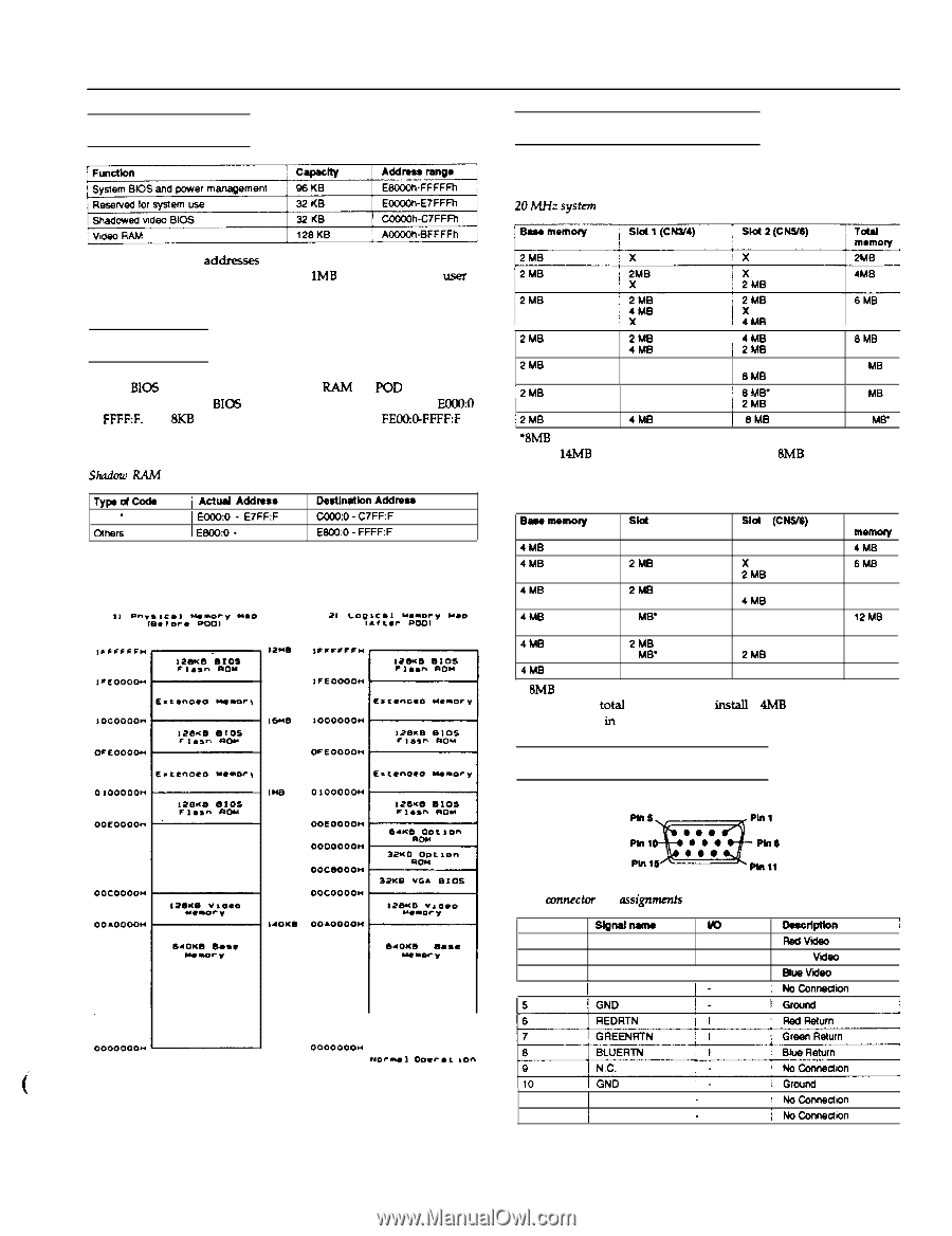
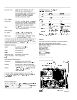
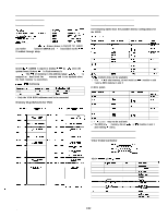
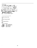
Reserved Memory NB-SL Notebook Computers Memory Module Expansion The following tables show the possible memory configurations for the NB-SL. Memory between the addresses shown above is reserved for system use. Other memory between 384KB and 1MB is available to the LWX if enabled through setup. Shadow RAM System BIOS (128KB) is copied to shadow RAh4 by POD when the system boots. System BIC5 in flash memory is addresses from ECU00 to FFFF:F. The 8KB of memory in the address range FEW@FFFF:F is assigned as a boot block for flash memory and is not updated when the flash memory is overwritten Shadow RAh4 Addressing Tywd- VGA ' j Actud Addrsts 1 E&W:0 - E7FF:F Destlnatlon Addmss cooO:O - C7FF:F Others 1 E84KtO - FFFF:F E8OO:O - FFFF:F l Only the VGA BIOS addresses need to be converted. Memory Map Before/After POD 2MB 2MB 4M0 ! 4MB / 2MB 8MB 2MB 8 MB' X X BMB 10 ME 12MB 2 MB 8 ME' ! 8MB' ! 2MB 12 MB ,2MB 4MB j 8MB 14 MB' '8MB modules may not be available. l * For 14h4B of total memory, do not install an 8MB module in slot 1 and a 4MB module in slot 2. 2.5 MHZ system Bsss msmoy Sld 1 (CHIN) Slot 2 (CNVS) Total memory 4MB X X 4M0 4MB 2MB X 2xMS 6MB 4M0 2MB X 2MB 4MB 8 MB" 4MB 8 MB' X X 8 MB' 12MB 4MB 2MB 8 MB' 8 MB' 2MB 14 MB 4MB 8 MB' 8 MB' 20 MB l SMB modules may not be available l * For 8MB of total memory, do not install a 4MB module in slot 1 and nothing in slot 2. Connector Pin Assignments VGA Video Connector i NB-SL Computers VGA mm&or pin assignments Pln no. sloti- m Dsscrlptlon !1 1 640X6 O..C t 1 2 RED GREEN I RSdVlt I Green V&o 3 BLUE I I Bus vlso 4 1 N.C. I - / NoConneUii ooooooo* L - - - J NoC"*I 0rlCr.c ,on 11 12 1 N.C. / N.C. _ : NoConnsdon _ / NoConnedton 1/92 NB-SL-3
-
 1
1 -
 2
2 -
 3
3 -
 4
4 -
 5
5 -
 6
6
 |
 |