Epson PowerLite 9000NL Product Information Guide - Page 3
Computer 1 and Computer Out Connector Pin Assignments, Projector Placement Guidelines
 |
View all Epson PowerLite 9000NL manuals
Add to My Manuals
Save this manual to your list of manuals |
Page 3 highlights
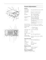
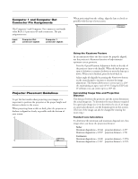
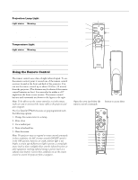
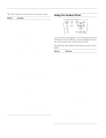
EPSON PowerLite 8000i/9000i Projector Computer 1 and Computer Out Connector Pin Assignments The Computer 1 and Computer Out connectors are female video RGB, 15-pin micro-D-style connectors. The pin assignments are: Input pin 1 2 3 4 5 6 7 8 9 10 11 12 13 14 15 Computer Out connector signals Red out / red video Green out / green video Blue out / blue video Reserved GND GND GND GND Reserved GND Reserved Reserved Horizontal sync Vertical sync Vertical sync Computer 1 connector signals Red video Green video Blue video Monitor (ID bit 2) GND Red video GND Green video GND Blue video GND +5 V Synchronous GND Monitor (ID bit 0) SDA Horizontal sync Vertical sync Reserved Projector Placement Guidelines To get the best results when projecting your images, it is important to position the projector at the proper height and distance relative to the screen. When projecting from a table or desk, place the projector so the lens is aligned as closely as possible with the bottom of your screen: When projecting from the ceiling, align the lens as closely as possible with the top of your screen: Using the Keystone Feature In circumstances where the lens cannot be properly aligned, use the projector's Keystone function to help maintain optimum screen geometry. t Press the Optical Keystone Adjustment knob on the side of the projector (next to the handle). When the knob pops out, turn it clockwise or counter-clockwise to move the lens up or down. When you're finished, press the knob back in. t Adjust angle tilt digitally by pressing the Keystone button on the control panel to increase or decrease the image adjustment. This feature allows you to correct up to a ±20° tilt, maintaining an aspect ratio of 4:3. Using the ELP Link IV software, you can correct up to a ±30° tilt. Calculating Image Size and Projection Distance The distance between the projector and the screen determines the actual image size. To determine the exact distance required for a particular image size (or to determine the size of an image at a particular distance), use the formulas given in this section. (The size of the image can also be changed by rotating the zoom ring.) Standard Lens Calculations To determine the minimum and maximum diagonal size of an image when you know the projection distance: t Inches: Maximum diagonal size = (0.642 × projection distance) + 2.197 Minimum diagonal size = (0.507 × projection distance) + 1.721 t Centimeters: Maximum diagonal size = (1.630 × projection distance) + 5.5356 Minimum diagonal size = (1.287 × projection distance) + 4.3713 10/99 EPSON PowerLite 8000i/9000i Projector - 3
-
 1
1 -
 2
2 -
 3
3 -
 4
4 -
 5
5 -
 6
6 -
 7
7 -
 8
8
 |
 |
