Epson TM-T20II UB-E03 Users Manual - Page 2
Caution
 |
View all Epson TM-T20II manuals
Add to My Manuals
Save this manual to your list of manuals |
Page 2 highlights
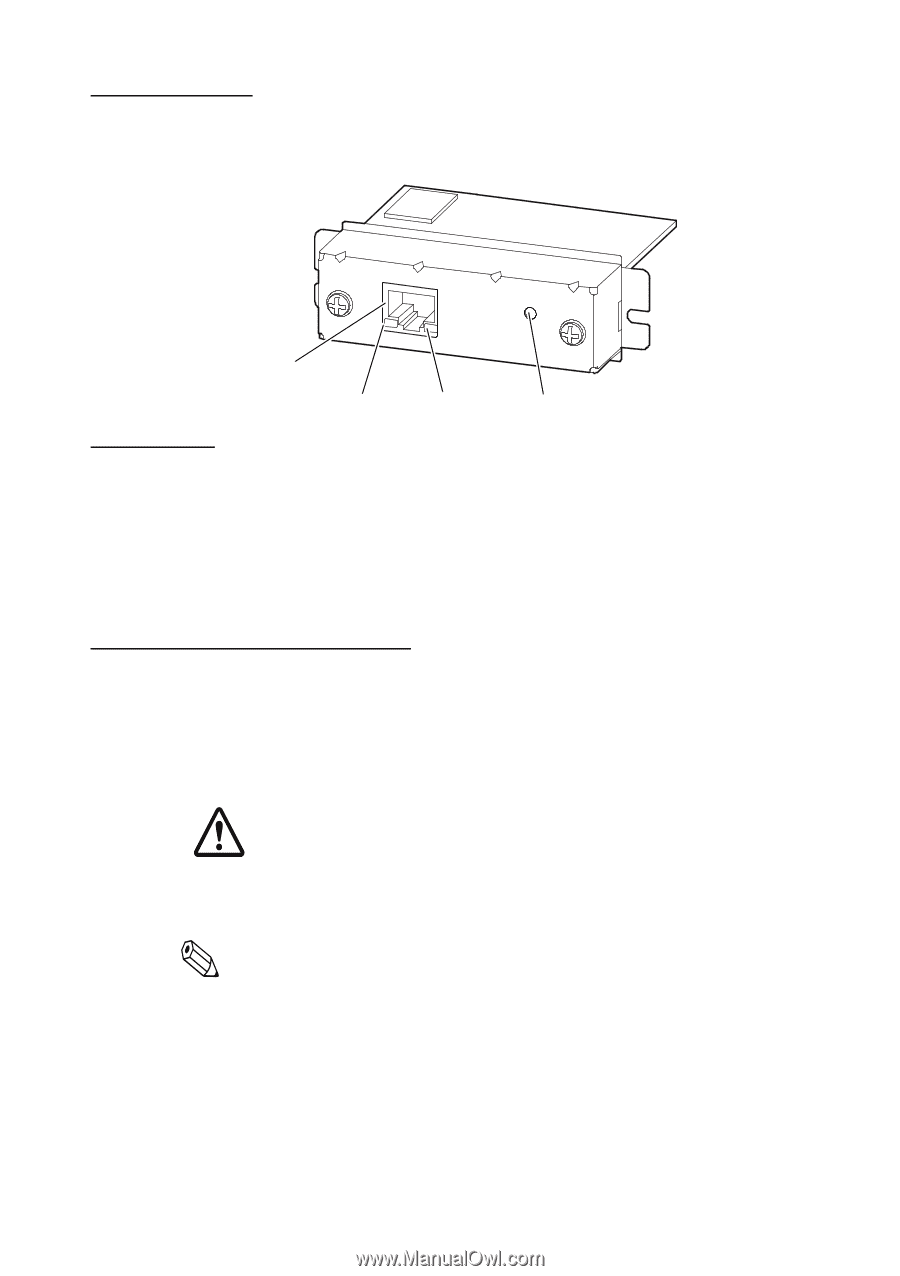
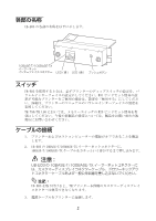
Part Names The following view shows the part names of the UB-E03. 10BASE-T/100BASE-TX Ethernet interface connector LED (green) LED (yellow) Push button Switches When using this interface board, the DIP switches of the TM printer must be set to "parallel" with the appropriate settings. Set the reset signal for pin 31 to "enabled" if you are using a TM printer that has this setting. Refer to the manual for your TM printer for details. For the TM-T90/L90/J7000/J7100/J7500/J7600 printers, set the reset signal for pin 25 of the memory switches to "enabled." For new models, please ask the dealer where you purchased your product. Connecting the Cables 1. Make sure both the printer and the host computer are turned off. 2. Plug the 10BASE-T/100BASE-TX cable connector securely into the UB-E03's 10BASE-T/100BASE-TX Ethernet connector until you feel it click. CAUTION: Do not connect a telephone line, a display module cable, or a drawer kick-out cable to the UB-E03's 10BASE-T/100BASE-TX Ethernet connector. Note: This display module connector on the TM printer cannot be used when the UB-E03 is installed. 3. Connect the power supply cable to the printer. 2
-
 1
1 -
 2
2 -
 3
3 -
 4
4 -
 5
5 -
 6
6 -
 7
7 -
 8
8
 |
 |