Eureka CV140 Yellow Jacket Owners Guide - Page 3
Ccaution - yellow jacket
 |
View all Eureka CV140 Yellow Jacket manuals
Add to My Manuals
Save this manual to your list of manuals |
Page 3 highlights
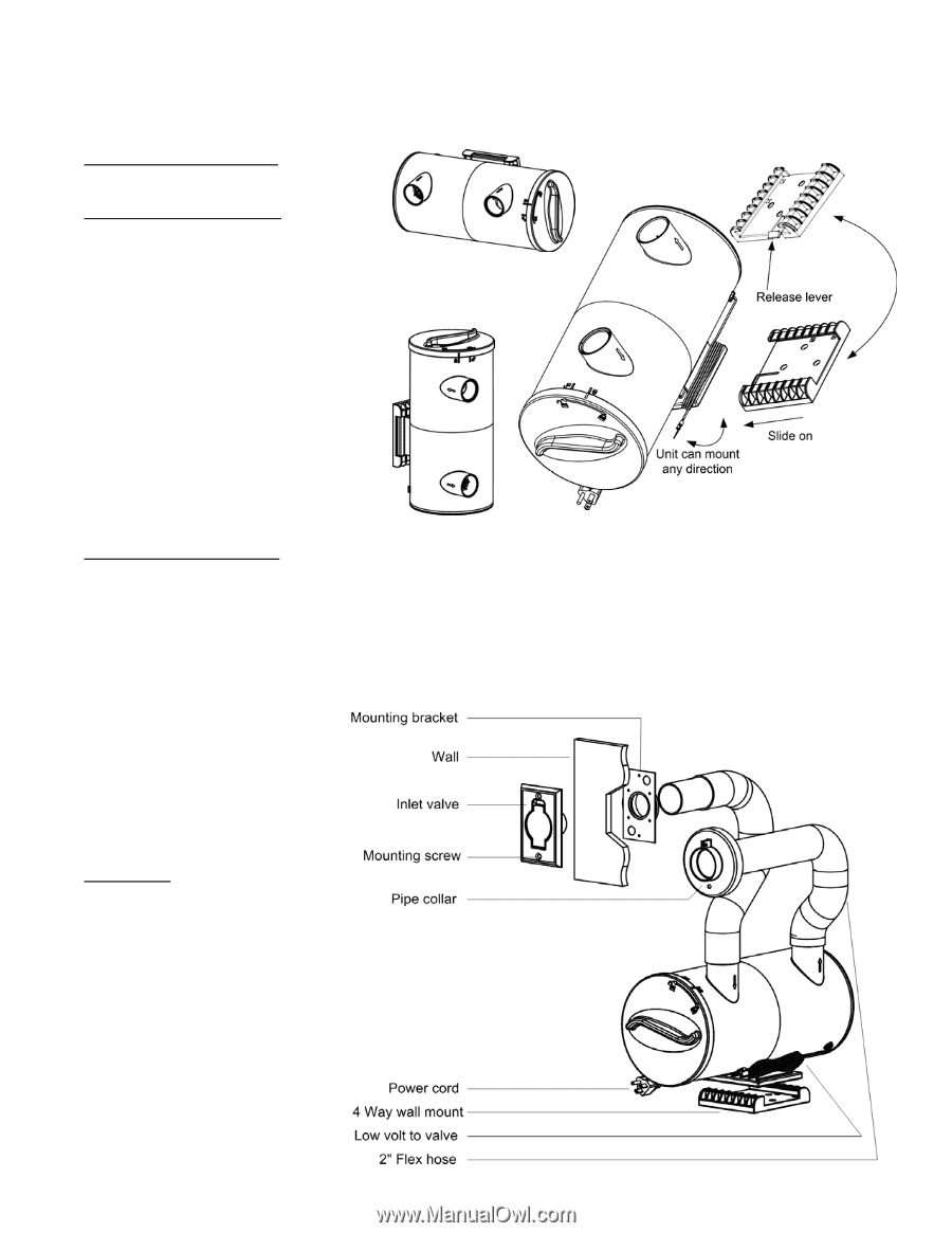
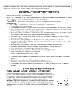
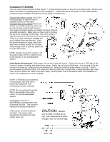
Installation PLANNING You can easily install a Eureka Yellow Jacket ™ central cleaning system in any new or existing coach. Please read these instructions completely before the first installation. These instructions are specific to the Yellow Jacket™ Central Vacuum installation instructions can be found on Eureka.com Choose Inlet Valve Location Use a 30 ft. measuring tape or vacuum hose to establish location of inlet valve. Choose Power Unit Location Power unit should be centrally located so that it can be conveniently reached with the hose. The power unit power supply cord needs to have a 120-volt grounded receptacle. Make sure you have room to remove the top lid for changing the filter bag. The Yellow Jacket ™ may be mounted in any of the three orientations pictured. There is a 4-way wall mount enabling the unit to slide in from any direction. Once the desired location is found, anchor the wall mount in place with (4) # 10 screws. Allow enough room to slide the power unit in to the wall mount. NOTE: Exhaust air must be vented - not through the floor of RV or mobile homes to the outside, or into closed/sealed spaces. Install Power Unit Important! Slide power unit into the 4-way wall mount. Connect flex hose or PVC pipe to the "arrow in" power unit intake and tighten hose clamp. Attach low volt wire to Wall valve. Join one end of the flex hose to the "arrow out" exhaust port on the power unit. Bend the hose and locate where to cut the 2" hole to accommodate vent/exhaust tube. Put collar over tube and slide tube through hole in wall and tighten pipe collar. Use a screw to fasten the collar to the wall. Finally, connect power cord to Grounded outlet. For installation of CV140 use installation kit number 040359. NOTE: A Thermal Cut-out protector is incorporated into each unit to protect the equipment from overheating or power overload. NOTE: Do not exhaust through the floor to the outside of the motor coach, or into enclosed/sealed spaces. Test System Vacuum is automatically activated when hose is inserted into inlet. This results in maximum cleaning convenience Check power unit inlet valves for operation. This power unit is intended for household, RV and mobile home use. CAUTION: MOUNT unit at least 2 inches (15.2 CAUTION: cm) from sidewalls and allow enough room to remMoOvUeNbTag. unit at least 2 inches (15.2 cm) from sidewalls and allow enough room to remove bag.
-
 1
1 -
 2
2 -
 3
3 -
 4
4
 |
 |