Fantec SNT-BA2131-1 Datasheet - Page 2
Picture E, J4: FAN RPM HIGH3600rpm & LOW2800rpm
 |
View all Fantec SNT-BA2131-1 manuals
Add to My Manuals
Save this manual to your list of manuals |
Page 2 highlights
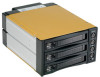
---Front Panel--- (see picture D) Picture E ---Rear View--- (see picture F) Picture F D.1--- Reset Switch for buzzer alarm and Overheating LED When overheating occurs the buzzer alarms (default setting: 60 and the temperature LED returns red meanwhile buzzer is alarming and LED is blinking). press the Reset Switch to stop the alarm, and LED goes off. D.2--- D.4 (HD1〜HD3, Power SW and LED: Power on, LED indicates Green. Orange color blinking for HDD access) D.5--- Fan sensor LED: LED is indicating Green when it is working. When fan fail, LED turns Red. D.6--- Safety Lock The safety lock safeguards the hard disk in the correct position and prevent it bouncing out while HDD is working. (see Picture E) POWER1: 4pin Power connector POWER2: 15pin Serial ATA Power connector HD1-HD3: 7pin Serial ATA Signal connector If your power is not from SATA 15pin connector, then, use the 4pin power connector, the 4pin power will automatically be convert to SATA power. (Note: Can mix using 4pin and 15pin powers) lJP1: Temperature setting jumper lJP3: Extension function jumper FLEDR: Fan failure detection (red) FLED+: Fan failure detection (+) FLEDG: Fan failure detection (green) RESET: Reset Switch for buzzer alarm and Overheating LED TLEDR: Temperature detection (red) 5V+: 5V Power TLEDG:Temperature detection (green) GND:Grounded J4: FAN RPM HIGH(3600rpm) & LOW(2800rpm) Optional
-
 1
1 -
 2
2
 |
 |
