Fantec SNT-BA3151-1 Datasheet - Page 2
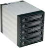
Picture D, RST: Reset Switch for buzzer alarm and Overheating LED
 |
View all Fantec SNT-BA3151-1 manuals
Add to My Manuals
Save this manual to your list of manuals |
Page 2 highlights
---Front Panel--- (see picture D, E) Picture D Picture E ---Rear View--- (see picture F) Picture F D.1--- D.5 (HD1〜HD5, Push On/Off Power SW) D.6--- Reset Switch for buzzer alarm and Overheating Press the Reset Switch to stop the alarm, and Overheating LED goes off. D.7--- D.11 Power and HDD access LED Power on, LED indicates Green. Orange color blinking for HDD access) D.12--- Overheating LED When overheating occurs, the buzzer alarms (default setting: 60°C and the temperature LED turns red meanwhile buzzer is alarming and LED is blinking). D.13--- Fan sensor LED: LED is indicating Green when it is working. When the fan failed, LED turns Red. D.14--- Safety Lock The safety lock safeguards the hard disk in the correct position and prevent it bouncing out while HDD is working. (see Picture E) POWER1: 4pin Power connector POWER2: 15pin Serial ATA data Power connector HD1-HD5: 7pin SATA / SAS Primary Signal connector If your power is not from SATA 15pin connector, then, use the 4pin power connector, the 4pin power will automatically be convert to SATA power. (Note: You can mix 4pin and)15pin power connector) lJP1: Temperature setting jumper lJP2 & J4: Extension function jumper FLR: Fan failure detection (red) FL+: Fan failure detection (+) FLG: Fan failure detection (green) RST: Reset Switch for buzzer alarm and Overheating LED TLR: Temperature detection (red) 5V+: 5V Power TLG: Temperature detection (green) GND: Grounded PL1- ~ PL5-: Ext Power LED detection (-) HL1- ~ HL5-: Ext HDD LED detection (-) VCC1- ~ VCC5-: Ext 5V Power (+) J5: FAN RPM HIGH (3600 rpm) & LOW (2800 rpm) Options
-
 1
1 -
 2
2
 |
 |
