Fisher and Paykel E522BRWFD5 User Guide - Page 17
into the water solenoid valve up
 |
View all Fisher and Paykel E522BRWFD5 manuals
Add to My Manuals
Save this manual to your list of manuals |
Page 17 highlights
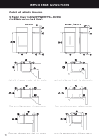
INSTALLATION INSTRUCTIONS !1 Attach double sided foam to the back of the water filter head as shown in Diagram 5. Write the date to be replaced on the filter (date installed + 6 months). Remove the double sided foam backing and 6 PART: 838587 attach the filter to the desired position, reinforcing the filter with the screws provided as located in step 10 (refer to the previous page). !2 Run the ¼" (6 mm) tubing to the back of the refrigerator ensuring there is enough tubing to pull the refrigerator out for service. !3 Using the measurement guide located on the rear compartment cover as shown in Diagram 6. Mark6 PART: 838587 out 5/8" (16 mm), on the end of the tubing as shown in Diagram 7. !4 Insert the tubing marked 5/8" (16 mm) into the water (solenoid) valve up to the marked line as shown in Diagram 8. !5 Pull gently on tubing to ensure it is locked in as shown in Diagram 9. !6 The completed installation should look like Diagram 11 on page 16. !7 Turn the isolating faucet on and check that all connections are dry and free of drips. !8 Coil water line tubing behind the refrigerator. Push your refrigerator into place being careful not to kink or squash the water line tube running into the water (solenoid) valve. !9 Read pages 16 - 17 carefully and then turn refrigerator on. PART: 838587 6 7 7 7 Diagram 6 Diagram 7 Diagram 8 EN DRAWING: 838587 8 9 Diagram 5 Double sided DRAWING: 838587 8 foam 9 attachment DRAWING: 838587 8 9 Diagram 9 Waterline connection to refrigerator 15
-
 1
1 -
2
-
3
-
4
-
5
-
6
-
7
-
8
-
9
-
10
-
11
-
 12
12 -
 13
13 -
 14
14 -
 15
15 -
 16
16 -
 17
17 -
 18
18 -
 19
19 -
 20
20 -
 21
21 -
 22
22 -
23
-
24
-
25
-
26
-
27
-
28
-
29
-
30
-
31
-
32
-
33
-
34
-
35
-
36
-
37
-
38
-
39
-
40
-
41
-
42
-
43
-
44
-
45
-
46
-
47
-
48
-
49
-
50
-
51
-
52
-
53
-
54
-
55
-
56
-
57
-
58
-
59
-
60
-
61
-
62
-
63
-
64
-
65
-
66
-
67
-
68
-
69
-
70
-
71
-
72
-
73
-
74
-
75
-
76
-
77
-
78
-
79
-
80
-
81
-
82
-
83
-
84
-
85
-
86
-
87
-
88
-
89
-
90
-
91
-
92
-
93
-
94
-
95
-
96
-
97
-
98
-
99
-
100
-
101
-
102
-
103
-
104
-
105
-
106
-
107
-
108
-
109
-
110
-
111
-
112
 |
 |
