Fluke 1625 FE 1625 Users Manual - Page 43
pole measurement with longer earth electrode connecting leads, Time average measurement
 |
View all Fluke 1625 manuals
Add to My Manuals
Save this manual to your list of manuals |
Page 43 highlights
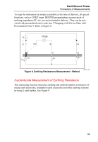
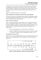
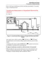
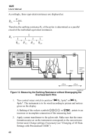
Earth/Ground Tester Procedure of Measurements An accuracy test of the results is made with another measurement following repositioning of the auxiliary earth electrode or probe. If the value stays the same, the distance is sufficient. If the measured value changes, probe or auxiliary earth electrode must be repositioned until the measured value RE stays constant. Spike wires should not run too close to each other. 3-pole measurement with longer earth electrode connecting leads Use one of the accessory cable drums as earth electrode connecting lead. Spool off cable completely and compensate line resistance as described in "Compensation of Earth Electrode Connecting Lead". Time average measurement: If there is a warning "measured value unstable" (see "Procedures of Measurement", "Description of display") after a test sequence, most likely it is caused by strong interference signals (e.g. unsteady noise voltage).Nevertheless, to get reliable values, the instrument offers the possibility of averanging over a longer period. 1. Select a fixed frequency (see "Control loop" in "Operation") 2. Keep the "START TEST" button pressed until the warning "measured value unstable" disappears. Max. averaging time is approx. 1 min. Evaluation of measured value: Figure 10 shows the maximum permissible value of the Earth resistance which will not exceed a permissible limit value, taking into account the maximum usage error. 0 10 Desired Values 20 50 100 200 500 1000 3000 3152 5 10 20 50 100 200 500 1000 2000 2999 Measured Values edw013.eps Figure 10. Earth Resistance - Maximum Permissible Value 35
-
 1
1 -
2
-
3
-
4
-
5
-
6
-
7
-
8
-
9
-
10
-
11
-
12
-
13
-
14
-
15
-
16
-
17
-
18
-
19
-
20
-
21
-
22
-
23
-
24
-
25
-
26
-
27
-
28
-
29
-
30
-
31
-
32
-
33
-
34
-
35
-
36
-
37
-
 38
38 -
 39
39 -
 40
40 -
 41
41 -
 42
42 -
 43
43 -
 44
44 -
 45
45 -
 46
46 -
 47
47 -
 48
48 -
49
-
50
-
51
-
52
-
53
-
54
-
55
-
56
-
57
-
58
-
59
-
60
-
61
-
62
-
63
-
64
-
65
-
66
-
67
-
68
-
69
-
70
-
71
-
72
-
73
-
74
-
75
-
76
-
77
-
78
-
79
-
80
-
81
-
82
-
83
-
84
-
85
-
86
-
87
-
88
-
89
-
90
 |
 |
