Fluke 1750 Fluke 1750 Three Phase Power Recorder Datasheet - Page 6
Specifications for the System, Recorder and Power Analyze Software - three phase power recorder
 |
View all Fluke 1750 manuals
Add to My Manuals
Save this manual to your list of manuals |
Page 6 highlights
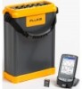
Specifications for the System: Recorder and Power Analyze Software General Power quality measurement standards Conformance IEC 61999-1-4 Class 1, IEC 61000-4-30, IEEE519, IEEE1159, IEEE1459 and EN50160 Clock/calendar Leap years, 24-hour clock Real-time clock accuracy Not more than ± 1 s/day Internal memory capacity for data At least 2 GB Maximum recording period At least 31 days Measurement time control Automatic Maximum number of events Limited only by the size of the internal memory Power requirements 100 to 240 V rms ± 10 %, 47-63 Hz, 40 W Operating time during interruptions (internal UPS operation) 5 minutes per interruption, 60 minutes total operating time without recharging Dimensions 215 mm x 310 mm x 35 mm (8.5 in x 12.2 in x 3.5 in) Mass (weight) 6.3 kg (14 lb) Input Measurement types Input channels Voltage channels Current input characteristics Measuring method One Phase Plus Neutral, One Phase IT No Neutral, One Phase Split Phase, Three Phase Wye, Three Phase Delta, Three Phase IT, Three Phase High Leg, Three Phase Open Leg, 2 Element Delta, 21/2 Element Wye Voltage: 4 channels, ac/dc Current: 5 channels Input resistance: 2 MΩ Input capacitance: < 20 pF 2 V rms = full scale, 1 MΩ Input Impedance for ferro CTs, low impedance for Flexi-CTs Simultaneous digital sampling of voltage and current. Digital PLL synchronized sampling, internal frequency reference used during voltage drops. Synchronization and sampling PLL-synchronization source PLL lock range Sampling frequency A/D resolution The PLL synchronizes to the A-N voltage for wye power types, and to the A-B voltage for delta power types. All listed power types can be characterized as either wye or delta. 42.5 to 69 Hz Voltage and current: 256 samples/cycle Inter-harmonics per IEC 61000-4-7: 2560 points/10 cycles (50 Hz), 3072 points/12 cycles (60 Hz) Transient Voltage: 5 MHz Voltage and current: 24 bits Transient voltage: 14 bits Voltage and current measurements Voltage measurement range AC voltage: 1000 V rms ± 10 % over range DC voltage: ± 1000 V + 10 % over range Voltage crest factor 3 or less Current measurement range Depends on current probe used Current crest factor 4 or less Voltage and current measurement accuracy RMS voltage Measurement type Measurement uncertainty RMS current Measurement type Measurement uncertainty True rms calculated continuously: every cycle, every 1/2 cycle, and every 10 or 12 cycles at 50 or 60 Hz respectively, as required by IEC 61000-4-30. AC: ± 0.2 % reading ± 0.1 % full scale, above 50 V rms DC: ± 0.5 % reading ± 0.2 % full scale, above 50 V dc True rms calculated continuously: every cycle, every 1/2 cycle, and every 10 or 12 cycles at 50 or 60 Hz respectively, as required by standards Ferromagnetic Clamps: ± (0.1 % full scale + 0.2 % reading + current sensor accuracy), valid for 5 % to 100 % of current sensor range Flexible Current Probes: ± (0.1 % full scale + 0.5 % reading + current sensor accuracy), valid for 5 % to 100 % of current sensor range 6 Fluke Corporation Fluke 1750 Three-Phase Power Recorder
-
 1
1 -
 2
2 -
 3
3 -
 4
4 -
 5
5 -
 6
6 -
 7
7 -
 8
8
 |
 |
