Fluke 179 Fluke Current Clamp Meters - Why True RMS Non-Linear Loads Need A Tr - Page 2
What is true-rms? - dmm
 |
View all Fluke 179 manuals
Add to My Manuals
Save this manual to your list of manuals |
Page 2 highlights
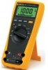
What is true-rms? "RMS" stands for root-meansquare. It comes from a mathematical formula that calculates the "effective" value (or heating value) of any ac wave shape. In electrical terms, the ac rms value is equivalent to the dc heating value of a particular waveform-voltage or current. For example, if a resistive heating element in an electric furnace is rated at 15 kW of heat at 240 V ac rms, then we would get the same amount of heat if we applied 240 V of dc instead of ac. Electrical power system components such as fuses, bus bars, conductors, and thermal elements of circuit breakers are rated in rms current because their main limitation has to do with heat dissipation. If we want to check an electrical circuit for overloading, we need to measure the rms current and compare the measured value to the rated value for the component in question. If a current clamp is labeled and specified to respond to the true-rms value of current, it means that the clamp's internal circuit calculates the heating value according to the rms formula. This method will give the correct heating value regardless of the current wave shape. Certain low-cost current clamps which don't have truerms circuitry use a short cut method to find the rms value. These meters are specified to be "average responding-rms indicating." These meters capture the rectified average of an ac waveform and scale the number by 1.1 to calculate the rms value. In other words, the value they display is not a true value, but rather is a calculated value based on an assumption about the wave shape. The average responding method works for pure sine waves but can lead to large reading errors up to 40 percent, when a waveform is distorted by nonlinear loads such as adjustable speed drives or computers. The table below gives some examples of the way the two different types of meters respond to different wave shapes. Current clamps come in two physical styles. The most common type is the integral clamp which has the jaws, readout, and measuring circuit built into a stand alone unit. Examples include Fluke Models 335, 336, and 337. Look for the words true-rms on the front panel. The second style consists of a current transformer (CT)type accessory which works with a digital multimeter. Examples include Fluke Models i200s, 80i-400, and 80i-600A. The jaws of the clamp enclose the conductor being measured which acts as a transformer primary of one turn. The secondary coil has 1,000 turns which divides the measured current by 1,000; i.e., the measured current is converted from amps to milliamps. When the clamp's output leads are plugged into the DMM's ac milliamp jacks, the display decimal reads correctly for amps in the jaws. Before you do that, make two other observations: First, analyze the load. If the load contains power semiconduc- tors, rectifiers, SCRs, etc., be suspicious of the current clamp reading. Second, look at the front panel of your current clamp-does it say true-rms? If you can't find the words true- rms on the front panel, then you probably have an average responding current clamp. (See Figure 4.) If you are Figure 4. The truerms clamp is labeled on the front panel. trying to meas- ure current drawn by a non-linear load containing semiconductors, without a true- rms meter, you are likely to make the wrong conclusion; that the problem is a faulty circuit breaker. Replacing the breaker won't help. You'll get a call-back with some unpleas- ant words from your customer. To avoid this, read the sidebar about true-rms, find your local Fluke distributor and get your- self a true-rms current clamp or meter that will give correct readings regardless of the type of load or current wave shape. If your reputation depends on accurate current readings then it won't take you long to decide that a true-rms multi- meter or current clamp is the only reasonable choice. Multimeter type Response to sine wave Response to square wave Response to single phase diode rectifier Response to 3 ∅ diode rectifier Average responding True-rms Correct Correct 10 % high Correct 40 % low Correct Figure 5. A comparison of average responding and true-rms units 5-30 % low Correct 2 Fluke Education Partnership Program Why true-rms? Fluke Corporation PO Box 9090, Everett, WA USA 98206 ©2003 Fluke Corporation. All rights reserved. Printed in U.S.A. 6/2003 2100101 A-ENG-N Rev A Web access: http://www.fluke.com
-
 1
1 -
 2
2
 |
 |
