Fluke 190-104/AM Product Manual - Page 5
Direct Input, V DC to 10 V DC Configuration
 |
View all Fluke 190-104/AM manuals
Add to My Manuals
Save this manual to your list of manuals |
Page 5 highlights
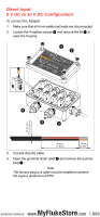
Direct Input 0 V DC to 10 V DC Configuration To connect the Adapter: 1. Make sure that all 4 mm safety test leads are disconnected. 2. Loosen the 4 captive screws and remove the lid to open the housing. 1 2 5 4 3 Ø 3-6 mm 0,12-0,24in 40mm 1,57in 10mm 0,39in 3. Cut and strip the cable. 4. Open the grommet strain relief and remove the dummy plug D. Note The dummy plug or a cable must be installed to achieve the ingress protection of IP50. MyFlukeStore e products online at: www. .com 1.888.6
-
 1
1 -
 2
2 -
 3
3 -
 4
4 -
 5
5 -
 6
6 -
 7
7 -
 8
8 -
 9
9 -
 10
10
 |
 |

Direct Input
0 V DC to 10 V DC Configuration
To connect the Adapter:
1.
Make sure that all 4 mm safety test leads are disconnected.
2.
Loosen the 4 captive screws
and remove the lid
to
open the housing.
3.
Cut and strip the cable.
4.
Open the grommet strain relief
and remove the dummy
plug
D
.
Note
The dummy plug or a cable must be installed to achieve
the ingress protection of IP50.
1
2
3
4
5
40mm
1,57in
10mm
0,39in
Ø 3-6 mm
0,12-0,24in
e products online at:
1.888.6
www.
MyFlukeStore
.com