Fluke PRV240 Product Manual - Page 1
Fluke PRV240 Manual
 |
View all Fluke PRV240 manuals
Add to My Manuals
Save this manual to your list of manuals |
Page 1 highlights
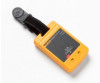
PRV240 Proving Unit Instruction Sheet Introduction The PRV240 Proving Unit (the Product) is an electronic voltage source. This Product provides a safe, risk free, and easy method to verify proper operation of a test tool. Use it to verify either an energized source or a de-energized source. Also use it in cases where no known voltage source is available to verify a test tool. The Product does not require personal protective equipment (PPE) unless your environment requires minimal PPE such as a hard hat, safety glasses, or ear plugs. Safety A Warning identifies conditions and procedures that are dangerous to the user. Warning To prevent possible electrical shock, fire, or personal injury: ●● Read all safety information before you use the Product. ●● Carefully read all instructions. ●● Do not alter the Product and use only as specified, or the protection supplied by the Product can be compromised. ●● Do not touch voltages >30 V ac rms, 42 V ac peak, or 60 V dc. ●● Do not use the Product around explosive gas, vapor, or in damp or wet environments. ●● Do not use the Product if it operates incorrectly. ●● Examine the case before you use the Product. Look for cracks or missing plastic. Carefully look at the insulation around the terminals. ●● Do not use the Product if it is altered or damaged. ●● Remove the batteries if the Product is not used for an extended period of time, or if stored in temperatures above 50 °C. If the batteries are not removed, battery leakage can damage the Product. ●● You must close and lock the battery door before you operate the Product. ●● Replace the batteries when the low battery indicator shows to prevent incorrect measurements. Symbols Symbols used in the instructions or on the Product are shown in Table 1. Table 1. Symbols Symbol Definition Risk of danger. Important information. See manual. Hazardous voltage. Battery Certified by CSA Group to North American safety standards. Conforms to relevant Australian EMC standards. Conforms to European Union directives. Conforms to relevant South Korean EMC Standards. This product complies with the WEEE Directive marking requirements. The affixed label indicates that you must not discard this electrical/electronic product in domestic household waste. Product Category: With reference to the equipment types in the WEEE Directive Annex I, this product is classed as category 9 "Monitoring and Control Instrumentation" product. Do not dispose of this product as unsorted municipal waste. Operation Table 2 shows the locations for the controls and interface of the Product. Use the Product to verify operation of a test tool at 240 V ac or 240 V dc. To use: 1. Select the AC or DC function with the selection switch on the side. 2. Place the red probe of the test tool into the (+) terminal and press down firmly. 3. Place the black probe of the test tool into the (-) terminal and press down firmly. 4. Make sure the meter reading of the Product is valid for the test function. For low impedance test tools, the output voltage should be sourced at >50 V ac or dc. It is recommended to test both the ac and dc functions of the test tool. Table 2. Overview of PRV240 1 4 SOURCE ONLY 2 3 Item Description hvj02.eps Voltage selection + Terminal − Terminal Power indicator Battery Installation/Replacement Warning To prevent possible electrical shock, fire, or personal injury: ●● Do not operate the Product with covers removed or the case open. Hazardous voltage exposure is possible. ●● Repair the Product before use if the battery leaks. ●● Have an approved technician repair the Product. To install or replace the batteries: 1. Turn the battery-door latch until the unlock symbol aligns with the arrow. 2. Lift off the battery door. 3. Insert or replace the four AA batteries. Use the correct battery orientation. 4. Install the battery door. 5. Turn the battery-door latch until the locked symbol aligns with the arrow. Specifications Output voltage 240 V ac rms or dc 10 % ≥1 MΩ LoZ >3 kΩ load 60 V ac typical 50 V ac rms minimum Output loading See Figure 1 LED power indicator Turns on when output voltage is present Battery 4 x AA Alkaline batteries NEDA 24 A IEC LR03 Battery life 5000 (5-second duration) test cycles with >1 MΩ load, 300 tests minimum with >3 kΩ load Operating temperature 10 °C to +50 °C Operating humidity 0 % to 90 % (0 °C to 35 °C) 0 % to 70 % (35 °C to 55 °C) Operating altitude 2000 m Dimensions 11.7 cm x 7.4 cm x 2.8 cm (4.6 in x 2.9 in x 1.1 in) Weight 0.23 kg (8 oz) includes batteries Safety IEC61010-1, IEC61010-2-030 300 250 200 V ac 150 100 50 Electromagnetic Compatibility (EMC) International IEC 61326-1: Controlled Electromagnetic Environment CISPR 11: Group 1, Class A Group 1: Equipment has intentionally generated and/or uses conductively-coupled radio frequency energy that is necessary for the internal function of the equipment itself. Class A: Equipment is suitable for use in all establishments other than domestic and those directly connected to a lowvoltage power supply network that supplies buildings used for domestic purposes. There may be potential difficulties in ensuring electromagnetic compatibility in other environments due to conducted and radiated disturbances. Caution: This equipment is not intended for use in residential environments and may not provide adequate protection to radio reception in such environments. Emissions that exceed the levels required by CISPR 11 can occur when the equipment is connected to a test object. Korea (KCC Class A Equipment (Industrial Broadcasting & Communication Equipment) Class A: Equipment meets requirements for industrial electromagnetic wave equipment and the seller or user should take notice of it. This equipment is intended for use in business environments and not to be used in homes. USA (FCC 47 CFR 15 subpart B. This product is considered an exempt device per clause 15.103. LIMITED WARRANTY AND LIMITATION OF LIABILITY This Fluke product will be free from defects in material and workmanship for one year from the date of purchase. This warranty does not cover fuses, disposable batteries, or damage from accident, neglect, misuse, alteration, contamination, or abnormal conditions of operation or handling. Resellers are not authorized to extend any other warranty on Fluke's behalf. To obtain service during the warranty period, contact your nearest Fluke authorized service center to obtain return authorization information, then send the product to that Service Center with a description of the problem. THIS WARRANTY IS YOUR ONLY REMEDY. NO OTHER WARRANTIES, SUCH AS FITNESS FOR A PARTICULAR PURPOSE, ARE EXPRESSED OR IMPLIED. FLUKE IS NOT LIABLE FOR ANY SPECIAL, INDIRECT, INCIDENTAL OR CONSEQUENTIAL DAMAGES OR LOSSES, ARISING FROM ANY CAUSE OR THEORY. Since some states or countries do not allow the exclusion or limitation of an implied warranty or of incidental or consequential damages, this limitation of liability may not apply to you. Fluke Corporation Fluke Europe B.V. P.O. Box 9090 Everett, WA 98206-9090 P.O. Box 1186 5602 BD Eindhoven U.S.A. The Netherlands 11/99 Fluke Corporation certifies this Product was tested and verified with applicable calibration procedures during the manufacturing process. Fluke's quality system controls these procedures. The instruments used during the testing and calibration of this Product are traceable to SI units through internationally recognized measurement standards. This document is not a certificate of calibration or traceability. To obtain a certificate of calibration contact the nearest Fluke service center to process an order to have your Product returned for calibration. A nominal fee is charged for calibration service. PN 4571866 November 2014, Rev. 1, 11/16 © 2014-2016 Fluke Corporation. All rights reserved. Product specifications are subject to change without notice. 0 1K 2K 10 K 100 K 1 M 10 M Load Resistance MyFlukeStore Shop for Fluke products online at: www. Figure 1. .com 1.888.610.7664
-
 1
1
 |
 |
