Foxconn ELA English Manual. - Page 24
a Connector : F_1394, S/PDIF Connector : SPDIF_OUT, IrDA Connector : IR, Serial ATA Connectors - pc
 |
View all Foxconn ELA manuals
Add to My Manuals
Save this manual to your list of manuals |
Page 24 highlights
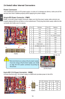
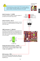
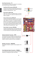
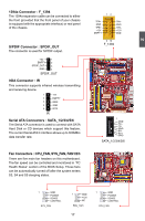
2 1394a Connector : F_1394 The 1394a expansion cable can be connected to either the front (provided that the front panel of your chassis is equipped with the appropriate interface) or real panel of the chassis. S/PDIF Connector : SPDIF_OUT The connector is used for S/PDIF output. +5V 1 EMPTY 2 SPDIF_OUT 3 GND 4 SPDIF_OUT IrDA Connector : IR This connector supports infrared wireless transmitting and receiving device. 1 +5V 2 EMPTY 3 IRRX 4 GND 5 IRTX IR Serial ATA Connectors : SATA_1/2/3/4/5/6 The Serial ATA connector is used to connect with SATA Hard Disk or CD devices which support this feature. The current Serial ATA II interface allows up to 300MB/s data transfer rate. Fan Connectors : CPU_FAN, SYS_FAN, FAN1/2/3 There are five main fan headers on this motherboard. The fan speed can be controlled and monitored in "PC Health Status" section of the BIOS Setup. These fans can be automatically turned off after the system enters S3, S4 and S5 sleeping states. 12 TPA+ GND TPB+ +12V EMPTY TPAGND TPB+12V GND 9 10 F_1394 1 GND TX+ TXGND RXRX+ GND SATA_1/2/3/4/5/6 1 GND POWER SENSE CONTROL SYS_FAN 1 GND +12V NC FAN_1/2/3 17 17 1 GND POWER SENSE CONTROL CPU_FAN
-
 1
1 -
2
-
3
-
4
-
5
-
6
-
7
-
8
-
9
-
10
-
11
-
12
-
13
-
14
-
15
-
16
-
17
-
18
-
 19
19 -
 20
20 -
 21
21 -
 22
22 -
 23
23 -
 24
24 -
 25
25 -
 26
26 -
 27
27 -
 28
28 -
 29
29 -
30
-
31
-
32
-
33
-
34
-
35
-
36
-
37
-
38
-
39
-
40
-
41
-
42
-
43
-
44
-
45
-
46
-
47
-
48
-
49
-
50
-
51
-
52
-
53
-
54
-
55
-
56
-
57
-
58
-
59
-
60
-
61
-
62
-
63
-
64
-
65
-
66
-
67
-
68
-
69
-
70
-
71
-
72
-
73
-
74
-
75
-
76
-
77
-
78
-
79
-
80
-
81
-
82
-
83
-
84
-
85
-
86
-
87
-
88
-
89
-
90
-
91
-
92
-
93
-
94
-
95
-
96
-
97
-
98
-
99
-
100
-
101
-
102
-
103
-
104
-
105
-
106
-
107
-
108
-
109
-
110
-
111
-
112
-
113
-
114
-
115
-
116
-
117
 |
 |
