Foxconn G41M-S English Manual. - Page 24
Fan Connectors : CPU_FAN, SYS_FAN - s3
 |
View all Foxconn G41M-S manuals
Add to My Manuals
Save this manual to your list of manuals |
Page 24 highlights
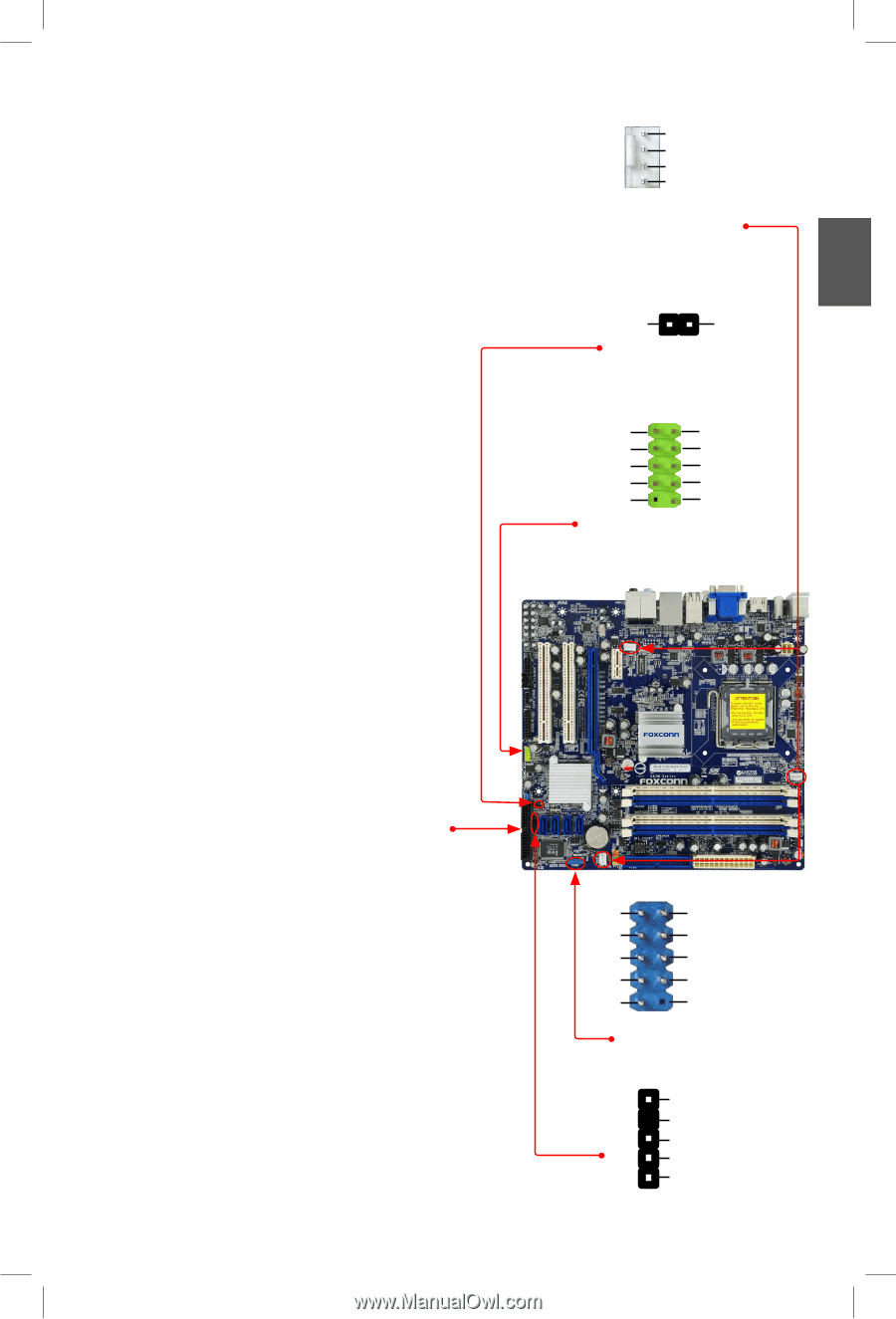
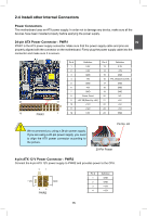
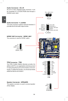
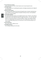
Fan Connectors : CPU_FAN, SYS_FAN, NB_FAN There are three main fan headers on this motherboard. The fan speed can be controlled and monitored in "PC Health Status" section of the BIOS Setup. These fans can be automatically turned off after the system enters S3, S4 and S5 sleeping states. Chassis Intrusion Alarm Connector : INTR The connector can be connected to a security switch on the chassis. The system can detect the chassis intrusion through the function of this connector. If eventually the chassis is closed, the system will send a message out. USB Connector : F_USB (G41M-S) In addition to the six USB ports on the rear panel, this product also provides one 10-pin USB header on its motherboard. By connecting through USB cables with them, user can quickly expand another two USB ports on the front panel. F_USB1/2 (G41M/G41M-V) In addition to the four USB ports on the rear panel, this product also provides two 10-pin USB header on its motherboard. By connecting through USB cables with them, user can quickly expand another four USB ports on the front panel. Floppy Disk Drive Connector : FLOPPY This motherboard includes a standard floppy disk drive (FDD) connector, supporting 360KB, 720KB, 1.2MB, 1.44MB, and 2.88MB FDDs. COM Connector : COM1 This motherboard supports one serial RS232 COM port for legacy compatibility. User must purchase another RS232 cable with a 9-pin D-sub connector at one end to connect with the external RS232 device and another end with 10-pin female connector to connect with COM2 connector in the motherboard. IR Connector : IR This connector supports infrared wireless transmitting and receiving device. 17 17 1 GND POWER SENSE CONTROL CPU_FAN/SYS_FAN/ NB_FAN INTRUDERJ 1 INTR GND 12 VCC DD+ GND EMPTY 9 10 F_USB VCC DD+ GND NC 12 RLSD SIN SOUT DTR GND DSR RTS CTS RI EMPTY 9 10 COM1 1 +5V 2 EMPTY 3 IRRX 4 GND 5 IRTX IR 2
-
 1
1 -
2
-
3
-
4
-
5
-
6
-
7
-
8
-
9
-
10
-
11
-
12
-
13
-
14
-
15
-
16
-
17
-
18
-
 19
19 -
 20
20 -
 21
21 -
 22
22 -
 23
23 -
 24
24 -
 25
25 -
 26
26 -
 27
27 -
 28
28 -
 29
29 -
30
-
31
-
32
-
33
-
34
-
35
-
36
-
37
-
38
-
39
-
40
-
41
-
42
-
43
-
44
-
45
-
46
-
47
-
48
-
49
-
50
-
51
-
52
-
53
-
54
-
55
-
56
-
57
-
58
-
59
-
60
-
61
-
62
-
63
-
64
-
65
-
66
-
67
-
68
-
69
-
70
-
71
-
72
-
73
-
74
-
75
 |
 |