Foxconn H55MX-S English Manual. - Page 23
TPM Connector : TPM, COM Connector : COM2 - pc
 |
View all Foxconn H55MX-S manuals
Add to My Manuals
Save this manual to your list of manuals |
Page 23 highlights
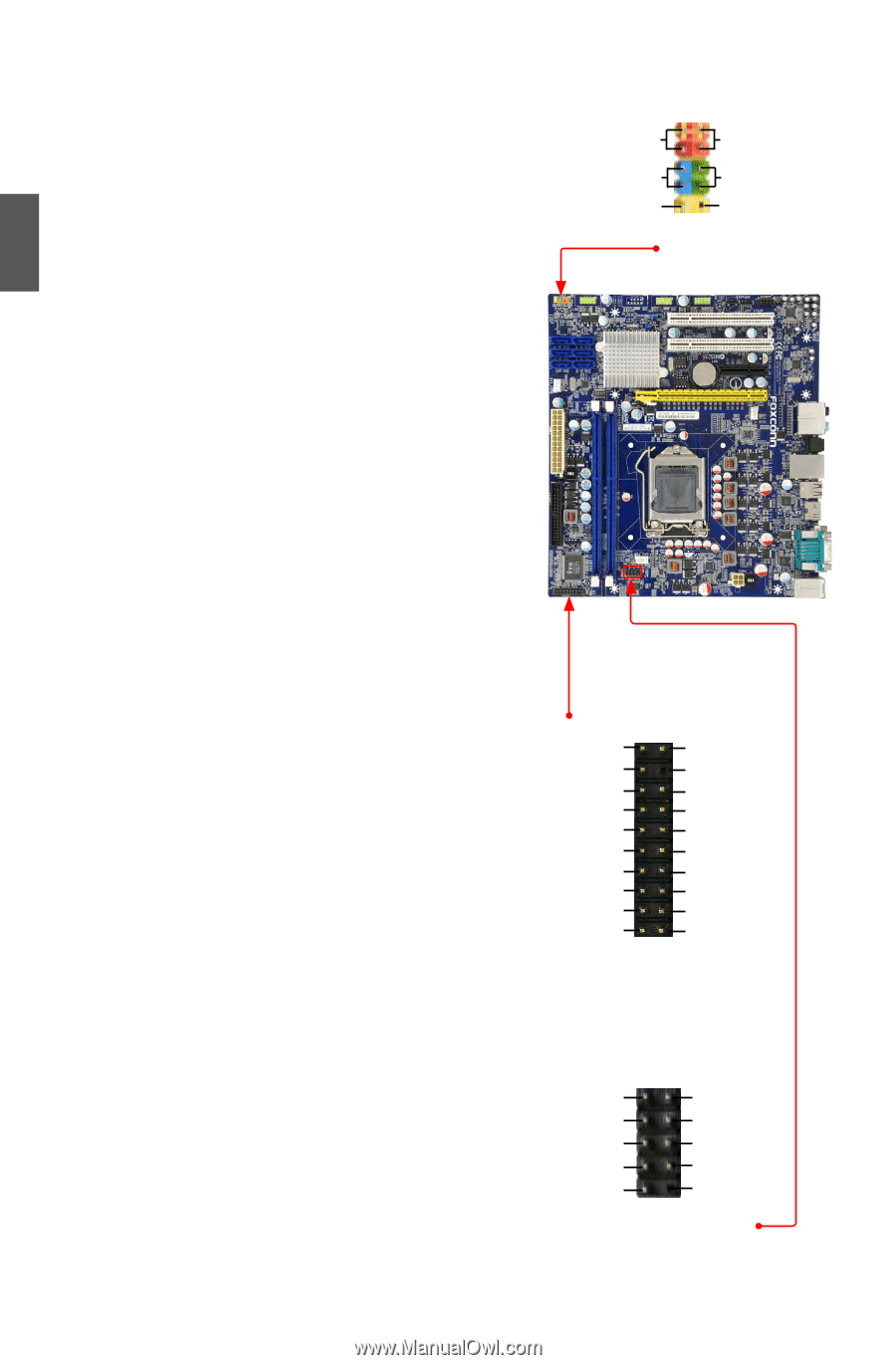
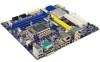
2 Front Panel Connector : FP1 This motherboard includes one connector for connecting the front panel switch and LED Indicators. Hard Disk LED Connector (HDD-LED) Connect to the chassis front panel IDE indicator LED. It indicates the active status of the hard disks. This 2-pin connector is directional with +/- sign. Reset Switch (RESET-SW) Attach the connector to the Reset switch on the front panel of the case; the system will restart when the switch is pressed. Power LED Connector (PWR-LED) Connect to the power LED indicator on the front panel of the chassis. The Power LED indicates the system's status. When the system is in operation (S0 status), the LED is on. When the system gets into sleep mode (S1) , the LED is blinking; When the system is in S3/S4 sleep state or power off mode (S5), the LED is off. This 2-pin connector is directional with +/- sign. Power Switch Connector (PWR-SW) Connect to the power button on the front panel of the chassis. Push this switch allows the system to be turned on and off rather than using the power supply button. TPM Connector : TPM The TPM (Trusted Platform Module) provides the ability to the PC to run applications more secure and to make transactions and communication more trustworthy. To utilize this function, you should purchase additional device and install it. 12 + + HDD-LED - PWR-LED - RESET-SW PWR-SW NC EMPTY 9 10 FP1 12 LCLK LFRAMEn LRESETn LAD3 VDD LAD0 NC_1 NC_2 GND LPCPDn 19 20 TPM GND EMPTY NC_3 LAD2 LAD1 GND NC_4 SERIRQ CLKRUNin NC_5 COM Connector : COM2 This motherboard supports one serial RS232 COM port for legacy compatibility. User must purchase another RS232 cable with a 9-pin D-sub connector at one end to connect with the external RS232 device and another end with 10pin female connector to connect with COM1 connector in the motherboard. 12 RLSD SIN SOUT DTR GND DSR RTS CTS RI EMPTY 9 10 COM2 16 16
-
 1
1 -
2
-
3
-
4
-
5
-
6
-
7
-
8
-
9
-
10
-
11
-
12
-
13
-
14
-
15
-
16
-
17
-
 18
18 -
 19
19 -
 20
20 -
 21
21 -
 22
22 -
 23
23 -
 24
24 -
 25
25 -
 26
26 -
 27
27 -
 28
28 -
29
-
30
-
31
-
32
-
33
-
34
-
35
-
36
-
37
-
38
-
39
-
40
-
41
-
42
-
43
-
44
-
45
-
46
-
47
-
48
-
49
-
50
-
51
-
52
-
53
-
54
-
55
-
56
-
57
-
58
-
59
-
60
-
61
-
62
-
63
-
64
-
65
-
66
-
67
-
68
-
69
-
70
-
71
-
72
-
73
 |
 |