Foxconn H61MD User manual - Page 22
Audio Header: F_AUDIO, Speaker Header: SPEAKER, Front Panel Header: FP
 |
View all Foxconn H61MD manuals
Add to My Manuals
Save this manual to your list of manuals |
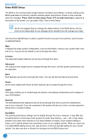
Page 22 highlights
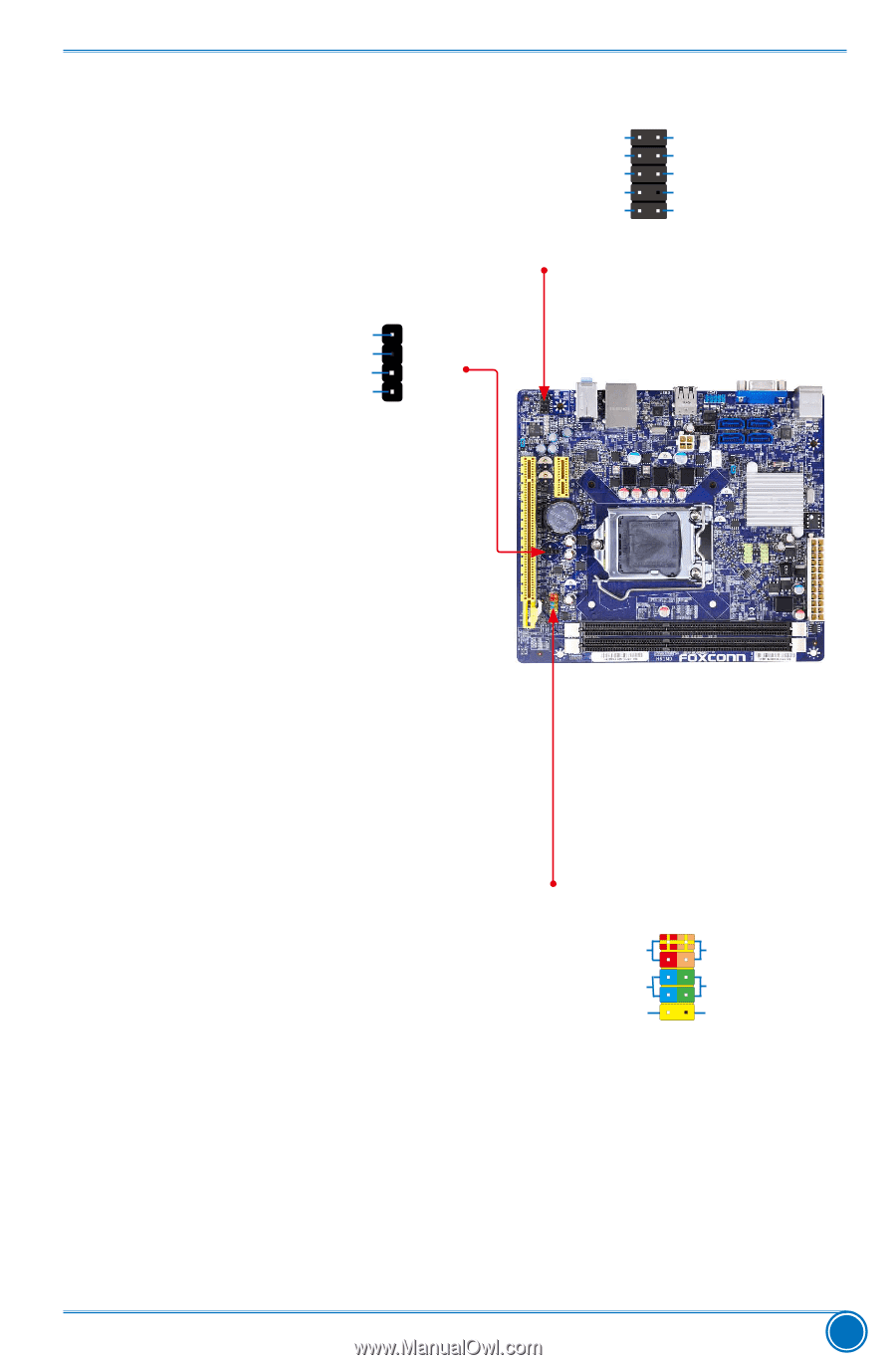
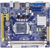
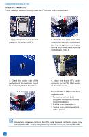
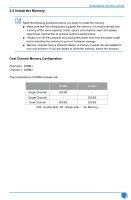
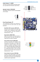
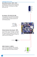
Audio Header: F_AUDIO The audio connector supports HD Audio standard. It provides the Front Audio output choice. Speaker Header: SPEAKER The speaker connector is used to connect speaker of the chassis. PWR 1 EMPTY 2 NC 3 SPKJ 4 SPEAKER Front Panel Header: FP This motherboard includes one connector for connecting the front panel switch and LED Indicators. Hard Disk LED Connector (HDD-LED) Connect to the chassis front panel IDE indicator LED. It indicates the active status of the hard disks. This 2-pin connector is directional with +/- sign. Reset Switch (RESET-SW) Attach the connector to the Reset switch on the front panel of the case; the system will restart when the switch is pressed. Power LED Connector (PWR-LED) Connect to the power LED indicator on the front panel of the chassis. The Power LED indicates the system's status. When the system is in operation (S0 status), the LED is on. When the system gets into sleep mode (S1) , the LED is blinking; When the system is in S3/S4 sleep state or power off mode (S5), the LED is off. This 2-pin connector is directional with +/- sign. Power Switch Connector (PWR-SW) Connect to the power button on the front panel of the chassis. Push this switch allows the system to be turned on and off rather than using the power supply button. HARDWARE INSTALLATION 12 A_MIC2_L AUD_GND A_MIC2_R A_LINE2_R PRESENCEJ SENSE1_RETURN SENSE_SEND EMPTY A_LINE2_L SENSE2_RETURN 9 10 F_AUDIO 12 + + HDD-LED - PWR-LED - RESET-SW PWR-SW NC EMPTY 9 10 FP 15
-
 1
1 -
2
-
3
-
4
-
5
-
6
-
7
-
8
-
9
-
10
-
11
-
12
-
13
-
14
-
15
-
16
-
 17
17 -
 18
18 -
 19
19 -
 20
20 -
 21
21 -
 22
22 -
 23
23 -
 24
24 -
 25
25 -
 26
26 -
 27
27 -
28
-
29
-
30
-
31
-
32
-
33
-
34
-
35
-
36
-
37
-
38
-
39
-
40
-
41
-
42
-
43
-
44
-
45
-
46
-
47
-
48
-
49
-
50
-
51
-
52
-
53
-
54
-
55
-
56
-
57
-
58
-
59
-
60
-
61
-
62
-
63
-
64
-
65
-
66
-
67
-
68
-
69
-
70
-
71
 |
 |