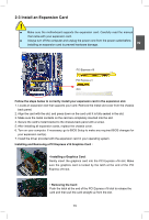
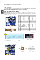
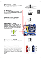
Foxconn H67M-S User manual - Page 23
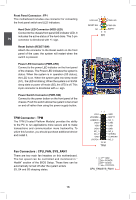
TPM Connector : TPM, Fan Connectors : CPU_FAN, SYS_FAN1
 |
View all Foxconn H67M-S manuals
Add to My Manuals
Save this manual to your list of manuals |
Page 23 highlights
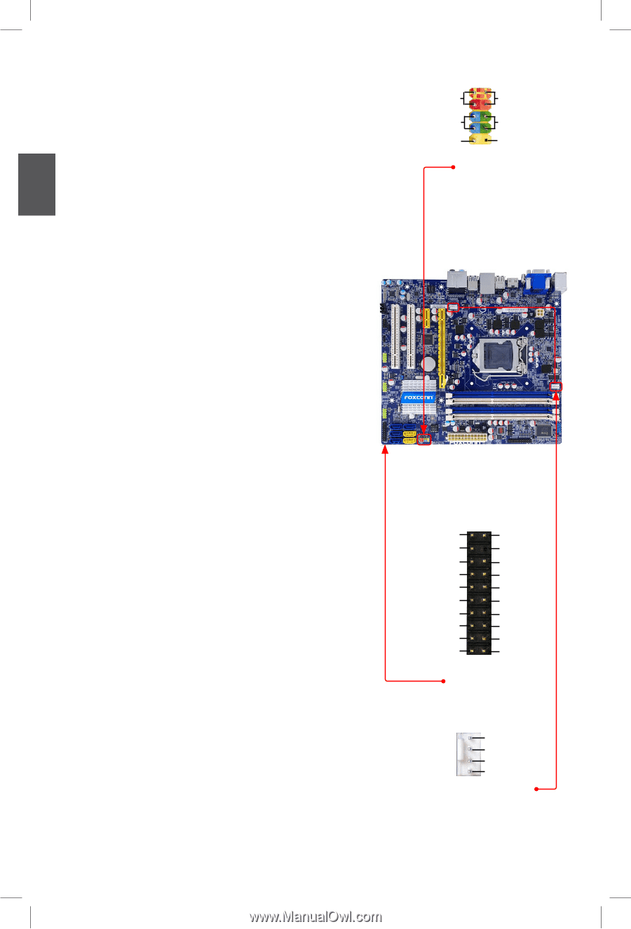
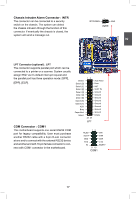
2 Front Panel Connector : FP1 This motherboard includes one connector for connecting the front panel switch and LED Indicators. Hard Disk LED Connector (HDD-LED) Connect to the chassis front panel IDE indicator LED. It indicates the active status of the hard disks. This 2-pin connector is directional with +/- sign. Reset Switch (RESET-SW) Attach the connector to the Reset switch on the front panel of the case; the system will restart when the switch is pressed. Power LED Connector (PWR-LED) Connect to the power LED indicator on the front panel of the chassis. The Power LED indicates the system's status. When the system is in operation (S0 status), the LED is on. When the system gets into sleep mode (S1) , the LED is blinking; When the system is in S3/S4 sleep state or power off mode (S5), the LED is off. This 2-pin connector is directional with +/- sign. Power Switch Connector (PWR-SW) Connect to the power button on the front panel of the chassis. Push this switch allows the system to be turned on and off rather than using the power supply button. TPM Connector : TPM The TPM (Trusted Platform Module) provides the ability to the PC to run applications more secure and to make transactions and communication more trustworthy. To utilize this function, you should purchase additional device and install it. Fan Connectors : CPU_FAN, SYS_FAN1 There are two main fan headers on this motherboard. The fan speed can be controlled and monitored in " Health" section of the BIOS Setup. These fans can be automatically turned off after the system enters S3, S4 and S5 sleeping states. 12 + + HDD-LED - PWR-LED - RESET-SW PWR-SW NC EMPTY 9 10 FP1 12 LCLK LFRAMEn LRESETn LAD3 VDD LAD0 NC_1 NC_2 GND LPCPDn 19 20 TPM GND EMPTY NC_3 LAD2 LAD1 GND NC_4 SERIRQ CLKRUNin NC_5 1 GND POWER SENSE CONTROL CPU_FAN/SYS_FAN1 16 16
-
 1
1 -
2
-
3
-
4
-
5
-
6
-
7
-
8
-
9
-
10
-
11
-
12
-
13
-
14
-
15
-
16
-
17
-
 18
18 -
 19
19 -
 20
20 -
 21
21 -
 22
22 -
 23
23 -
 24
24 -
 25
25 -
 26
26 -
 27
27 -
 28
28 -
29
-
30
-
31
-
32
-
33
-
34
-
35
-
36
-
37
-
38
-
39
-
40
-
41
-
42
-
43
-
44
-
45
-
46
-
47
-
48
-
49
-
50
-
51
-
52
-
53
-
54
-
55
-
56
-
57
-
58
-
59
-
60
-
61
-
62
-
63
-
64
-
65
-
66
-
67
-
68
-
69
-
70
-
71
-
72
-
73
-
74
-
75
-
76
-
77
-
78
-
79
-
80
-
81
-
82
-
83
-
84
-
85
-
86
-
87
-
88
-
89
-
90
-
91
-
92
-
93
-
94
-
95
-
96
-
97
-
98
-
99
-
100
-
101
-
102
-
103
-
104
-
105
-
106
-
107
-
108
-
109
 |
 |