Foxconn P43A-S English Manual. - Page 23
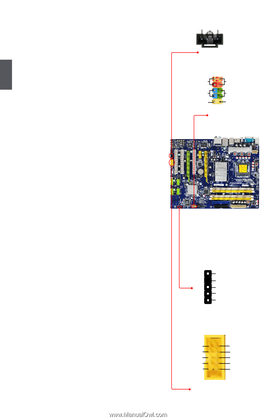
Audio Connector : CD_IN, Front Panel Connector : FP1, IrDA Connector : IR, 1394a Connector : F_1394
 |
View all Foxconn P43A-S manuals
Add to My Manuals
Save this manual to your list of manuals |
Page 23 highlights
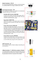
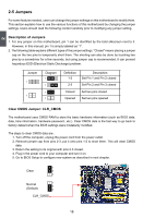
2 Audio Connector : CD_IN CD_IN is a Sony standard audio connector, it can be connected to a CD/DVD-ROM drive through a CD/DVD audio cable. Front Panel Connector : FP1 This motherboard includes one connector for connecting the front panel switch and LED Indicators. Hard Disk LED Connector (HDD-LED) Connect to the chassis front panel IDE indicator LED. It indicates the active status of the hard disks. This 2-pin connector is directional with +/- sign. Reset Switch (RESET-SW) Attach the connector to the Reset switch on the front panel of the case; the system will restart when the switch is pressed. Power LED Connector (PWR-LED) Connect to the power LED indicator on the front panel of the chassis. The Power LED indicates the system's status. When the system is in operation (S0 status), the LED is on. When the system gets into sleep mode (S1) , the LED is blinking; When the system is in S3/S4 sleep state or power off mode (S5), the LED is off. This 2-pin connector is directional with +/- sign. Power Switch Connector (PWR-SW) Connect to the power button on the front panel of the chassis. Push this switch allows the system to be turned on and off rather than using the power supply button. IrDA Connector : IR This connector supports infrared wireless transmitting and receiving device. 1394a Connector : F_1394 (Only available in P43A-S) The 1394a expansion cable can be connected to either the front (provided that the front panel of your chassis is equipped with the appropriate interface) or real panel of the chassis. CD_L GND CD_R 1 CD_IN 12 + + HDD-LED - PWR-LED - RESET-SW PWR-SW NC EMPTY 9 10 FP1 1 2 3 4 5 IR +5V EMPTY IRRX GND IRTX 12 TPA+ GND TPB+ +12V EMPTY TPAGND TPB- +12V GND 9 10 F_1394 16
-
 1
1 -
2
-
3
-
4
-
5
-
6
-
7
-
8
-
9
-
10
-
11
-
12
-
13
-
14
-
15
-
16
-
17
-
 18
18 -
 19
19 -
 20
20 -
 21
21 -
 22
22 -
 23
23 -
 24
24 -
 25
25 -
 26
26 -
 27
27 -
 28
28 -
29
-
30
-
31
-
32
-
33
-
34
-
35
-
36
-
37
-
38
-
39
-
40
-
41
-
42
-
43
-
44
-
45
-
46
-
47
-
48
-
49
-
50
-
51
-
52
-
53
-
54
-
55
-
56
-
57
-
58
-
59
-
60
-
61
-
62
-
63
-
64
-
65
-
66
-
67
-
68
-
69
-
70
-
71
-
72
-
73
-
74
 |
 |