Foxconn R10-D1 Easyguide.
Foxconn R10-D1 Manual
 |
View all Foxconn R10-D1 manuals
Add to My Manuals
Save this manual to your list of manuals |
Foxconn R10-D1 manual content summary:
- Foxconn R10-D1 | Easyguide. - Page 1
R10-D1 * Bezel View SPECIFICATION M/B Configuration local city office, your household waste disposal service or the shop where you purchased this release another bottom clip. 4. Detach the card reader cable from the motherboard. 5. Remove two screws to detach the driver bay. 6. Push driver - Foxconn R10-D1 | Easyguide. - Page 2
ßen Sie ein anderes Ende des SATA-Kabels und das Stromkabel an ODD an. 6.4 Schließen Sie das Kartenleserkabel an den USB-Anschluss des Motherboards an. 6.5 Befestigen Sie den Laufwerkschacht und das Gehäuse mit zwei Schrauben. 7. Gehäuse neuinstallieren 7.1 Entfernen Sie die ODD-Frontplatte von der
-
 1
1 -
 2
2
 |
 |
3
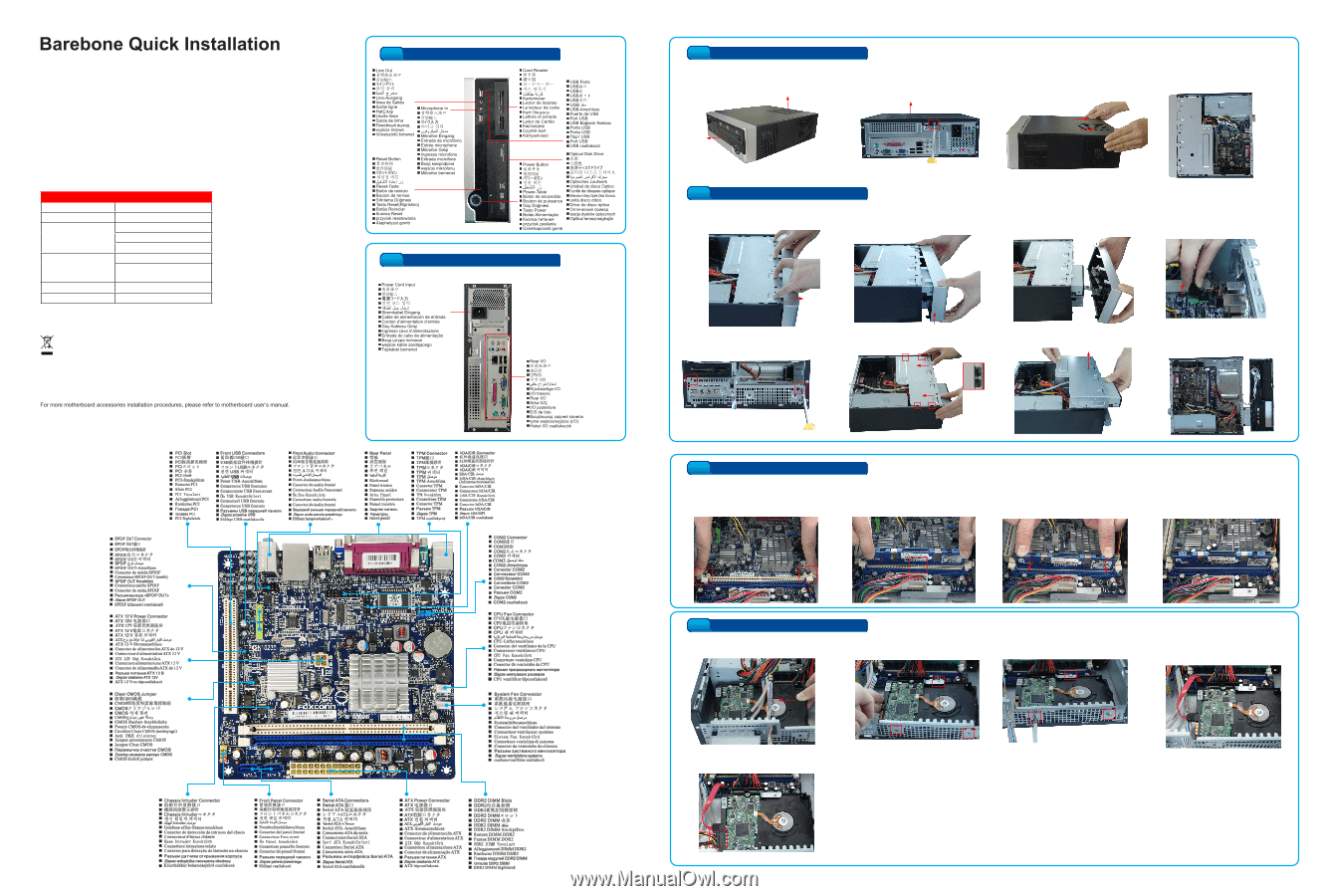
Install Memory
4. The clips at both ends of the socket will
snap into place when the memory module
is securely inserted.
3. Place the memory module onto the
socket, then push it down firmly and
seat it vertically into the memory
socket.
1. �pread the clips at both ends of the
�pread the clips at both ends of the
memory socket.
2. Memory module has asymmetric pin
counts in its two sides separated by a
notch in the middle, so it can only fit in
one direction.
4
Install Hard Disk Drive (HDD)
1. Put the ±²² into the chassis as depicted
Put the ±²² into the chassis as depicted
in the picture.
3. ³asten the ±²² with three screws.
³asten the ±²² with three screws.
2. Move the ±²² to ali´n with three
ove the ±²² to ali´n with three
screw holes.
4. Use provided shorter �ATA cable to
connect motherboard and ±²².
5. Connect power cable to ±²².
WEEE:
The use of this symbol indicates that this product may not be treated as household waste. By ensurin´ this product
is disposed of correctly, you will help prevent potential ne´ative consequences for the environment and human
health, which could otherwise be caused by inappropriate waste handlin´ of this product. ³or more detailed
information about recycling of this product, please contact your local city office, your household waste disposal
service or the shop where you purchased this product.
All image are for reference only, please refer to the physical chassis for specific features.
�PECI³ICATION
M/B Configuration
Mini ITX MB
²imension (W/±/²)
95*280*282mm (W/O Bezel)
²rive Bays
1*5.25" External
1*3.5" External (�hort)
1*3.5" Internal
³ront I/O Ports
2*U�B2.0
1* Micphone,
1* Earphone
�P�
³�P150-50GLT
³an
80*80*20mm
3. Remove the top cover by pushin´ it toward
real panel, and lift it.
4. Check there are motherboard, power
supply and driver bay inside.
2. Remove the top cover screw on the
Remove the top cover screw on the
real panel.
1.
Take the chassis out of its packin´.
³ront
Panel
Top cover (or �ide Panel)
Top cover
1
Open the case
2
Remove Bezel and Driver Bay
1.
Release four clips on the bezel top.
2.
±old the bezel with both hands, lift
left hand side to release two bottom
clips.
3.
Lift ri´ht hand side to release another
bottom clip.
5.
Remove two screws to detach
the driver bay.
6. Push driver bay toward real panel and lift it
to remove.
7. Now, you can start the installations of
memory, hard drive and optical disk drive.
*
Bezel View
*
Rear Panel View
P/N:3A2512±00-G8W-G
:3A2512±00-G8W-G
4.
²etach the card reader cable from
the motherboard.
R10-D1