Foxconn R10-S2 R10-S2 Easyguide - Page 1
Foxconn R10-S2 Manual
 |
View all Foxconn R10-S2 manuals
Add to My Manuals
Save this manual to your list of manuals |
Page 1 highlights
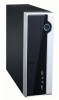
Small Form Factor Barebone Chassis Quick Installation SFF R10-S2 SPECIFICATION M/B Configuration Mini ITX MB Dimension (W/H/D) 283*282*95 (mm) 1*5.25" External Drive Bays 1*3.5" External 1*3.5" Internal Front I/O Ports 2*USB2.0 1* Micphone, 1*Earphone SPS TFX 150W Fan 80*80*20mm WEEE: The use of this symbol indicates that this product may not be treated as household waste. By ensuring this product is disposed of correctly, you will help prevent potential negative consequences for the environment and human health, which could otherwise be caused by inappropriate waste handling of this product. For more detailed information about recycling of this product, please contact your local city office, your household waste disposal service or the shop where you purchased this product. All image are for reference only, please refer to the physical chassis for specific features. P/N: 3A250J000-000-G * Bezel View USB Port USB接口 USB埠 USBポット USB포트 USB-Anschluss Puerto de USB Port USB USB Bağlantı Noktası Porta USB Porta USB Порт USB Port USB USB csatlakozó Reset Button Reset-Taste Botón de reinicio Bouton de remise Sıfırlama Düğmesi Tasto Reset(Ripristino) Botão Reiniciar Reset przycisk resetowania Alaphelyzet gomb * Rear Panel View Rear I/O I/O 후면 I/O Rückwärtige I/O I/O trasero Rear I/O Arka G/Ç I/O posteriore E/S de trás tylne wejście/wyjście (I/O) Hátsó I/O csatlakozók Line Out Line-Ausgang linea de Salida Sortie ligne HatÇıkışı Uscita linea Saída de linha wyjście liniowe Vonalszintű kimenet Power Button Power-Taste Botón de encendido Bouton de puissance Güç Düğmesi Tasto Power Botão Alimentação przycisk zasilania Üzemkapcsoló gomb Microphone In Mikrofon-Eingang Entrada de micrófono Entrée microphone Mikrofon Girişi Ingresso microfono Entrada microfone wejście mikrofonu Mikrofon bemenet Optical Disk Drive 光驱 Optisches Laufwerk Unidad de disco Optico l'unité de disques optique Mikrofon Girişi Optik Disk Sürücü unità disco ottico Drive do disco óptico stacja dysków optycznych Optikai lemezmeghajtó Power Cord Input Stromkabel Eingang Cable de alimentación de entrada Cordon d'alimentation d'entrée Güç Kablosu Girişi ingresso cavo d'alimentazione Entrada do cabo de alimentação wejście kabla zasilającego Tápkábel bemenet 1 Open the case 1. Take the chassis out of its packing. 2. Remove the top cover screw on the real panel. 3. Remove the top cover by pushing it toward real panel, and lift it. Top cover (or Side Panel) Top cover 4. Check there are motherboard, power supply and driver bay inside. Front Panel 2 Remove Bezel and Driver Bay 1. Release four clips on the bezel top. 2. Hold the bezel with both hands, lift left hand side to release two bottom clips. 3. Lift right hand side to release another bottom clip. 4. Remove two screws to detach the driver bay. 5. Push driver bay toward real panel and lift it to remove. 6. Now, you can start the installations of memory, hard drive and optical disk drive. 3 Install Memory 1. Spread the clips at both ends of the memory socket. 2. Memory module has asymmetric pin counts in its two sides separated by a notch in the middle, so it can only fit in one direction. 3. Place the memory module onto the socket, then push it down firmly and seat it vertically into the memory socket. 4. The clips at both ends of the socket will snap into place when the memory module is securely inserted. 4 Install Hard Disk Drive (HDD) 1. Put the HDD into the chassis as depicted in the picture. 2. Move the HDD to align with three screw holes. 3. Fasten the HDD with three screws. 4. Use provided shorter SATA cable to connect motherboard and HDD. 5. Connect power cable to HDD.
-
 1
1 -
 2
2
 |
 |