Foxconn Z75M-S User manual - Page 23
TPM Header : TPM1, USB 2.0 Connectors: F_USB1/2, Front Panel Connector : FP1
 |
View all Foxconn Z75M-S manuals
Add to My Manuals
Save this manual to your list of manuals |
Page 23 highlights
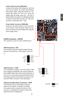
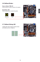
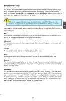
2 TPM Header : TPM1 The TPM (Trusted Platform Module) provides the ability to the PC to run applications more secure and to make transactions and communication more trustworthy. To utilize this function, you should purchase additional device and install it. USB 2.0 Connectors: F_USB1/2 These connectors comply with USB 2.0 specification, you can get USB ports by connecting the USB module cable to any of these connectors. F_USB2 support USB Charger function, for the detailed information, please refer to the USB Charger Introduction in Appendix. 12 12 VCC DD+ GND EMPTY VCC DD+ GND NC VCC DD+ GND EMPTY VCC DD+ GND NC 9 10 F_USB1 9 10 F_USB2 LCLK LFRAMEn LRESETn LAD3 VDD LAD0 NC_1 NC_2 GND LPCPDn 12 19 20 TPM GND EMPTY NC_3 LAD2 LAD1 GND NC_4 SERIRQ CLKRUNin NC_5 USB 3.0 Connectors: USB 3.0 This connector complies with the USB 3.0 specifi- cation, and is for the additional USB 3.0 ports. 19 20 NC USB2.0 D+ USB2.0 D+ USB2.0 D- USB2.0 D- GND GND USB3.0 SS TX+ USB3.0 SS TX+ USB3.0 SS TX- USB3.0 SS TX- GND GND USB3.0 SS RX+ USB3.0 SS RX+ USB3.0 SS RX- USB3.0 SS RX- VCC VCC EMPTY 1 2 USB 3.0 Front Panel Connector : FP1 This motherboard includes one connector for connecting the front panel switch and LED Indicators. Hard Disk LED Connector (HDD-LED) Connect to the chassis front panel IDE indicator LED. It indicates the active status of the hard disks. This 2-pin connector is directional with +/- sign. 12 + HDD-LED - + PWR-LED - RESET-SW PWR-SW NC EMPTY 9 10 FP1 Reset Switch (RESET-SW) Attach the connector to the Reset switch on the front panel of the case; the system will restart when the switch is pressed. 16
-
 1
1 -
2
-
3
-
4
-
5
-
6
-
7
-
8
-
9
-
10
-
11
-
12
-
13
-
14
-
15
-
16
-
17
-
 18
18 -
 19
19 -
 20
20 -
 21
21 -
 22
22 -
 23
23 -
 24
24 -
 25
25 -
 26
26 -
 27
27 -
 28
28 -
29
-
30
-
31
-
32
-
33
-
34
-
35
-
36
-
37
-
38
-
39
-
40
-
41
-
42
-
43
-
44
-
45
-
46
-
47
-
48
-
49
-
50
-
51
-
52
-
53
-
54
-
55
-
56
-
57
-
58
-
59
-
60
-
61
-
62
-
63
-
64
-
65
-
66
-
67
-
68
-
69
-
70
-
71
-
72
-
73
-
74
-
75
-
76
-
77
-
78
-
79
-
80
-
81
-
82
-
83
-
84
-
85
-
86
-
87
-
88
-
89
-
90
-
91
-
92
-
93
-
94
-
95
-
96
-
97
-
98
-
99
-
100
-
101
-
102
-
103
-
104
-
105
-
106
-
107
-
108
-
109
-
110
 |
 |
