Foxconn nT-i1250 Easy guide - Page 1
Foxconn nT-i1250 Manual
 |
View all Foxconn nT-i1250 manuals
Add to My Manuals
Save this manual to your list of manuals |
Page 1 highlights
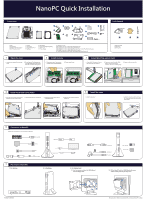
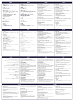
Components 6 8 5 7 9 Tools Needed 10 13 A B C D 11 14 12 1. HDD 2. HDD Bracket 3. Mini PCIe Half Card Support 4. Mini PCIe add-on Card 5. Memory 6. Screw cover 7. Magnet Rubber Foot 8. Seatbase 9. VESA Mount 10. DVI to VGA Adapter(Optional) 11. Power Cord 12. Power Adapter 13. Screw(A, B, C, D) A. M2.43X4.85 mm (9x): To fasten HDD Bracket and Case B. M2.92X2.85 mm (3x): To fasten HDD to HDD Bracket C. M2.42X2.85 mm (1x): To fasten Mini PCIe add-on Card to Mini PCIe Half Card Support D. M3.90X9.70 mm (4x): To fasten VESA Mount to display 14. USB Flash Disk(With Driver, Utility, User's Manual and Easy Guide in it) 1. ESD Wrist Strap 2. ESD Gloves 3. Opening Tool 1 Open the case 1. Unscrew four screws (A) on the top cover. 2. Put an Opening Tool between the cover and case then move it to the other side to remove the top cover. 2 Install memory 1. Plug the pin side of the memory module into the socket slantwise. 2. Press it down firmly. 3 Install Mini PCIe add-on Card 1. Fasten Mini PCIe add-on Card to Mini PCle Half Card Support. 2. Plug the pin side of the Mini PCIe add-on Card into the socket slantwise, then press it down gently. 3. Fasten it with one screw (A). B A A B 4 Install Hard Disk Drive (HDD) 1. Insert the HDD into the HDD bracket 2. Fasten them with three screws (B). slantwise first, then press it down. 3. Install HDD into the socket on the motherboad gently. 4. Fasten the HDD bracket with four screws (A). 5 Install the case 1. Install the top cover. A B A B 2. Fasten the top cover with four screws (A) . Stick the screw cover on the four screw holes. A B 6 Connection of NanoPC Please refer to the diagram to connect devices to NanoPC. USB Keyboard Display LAN Power adapter USB Mouse HD TV Speaker device 7 Placement of NanoPC 1. On tabletop 2. In Seatbase USB devices Microphone Headphone USB Flash Disk Memory card SD/MMC/MS 3. On display back 3.1. Use four screws to fasten the VESA Mount onto the display back. 3.2. Fit the NanoPC into the VESA Mount with power button locating at the top for easy touch. B A P/N:3A251KH00-000-G All images are for reference only, please refer to the physical NanoPC for detail.
-
 1
1 -
 2
2
 |
 |
