Frigidaire FAQE7011KW Installation Instructions (All Languages) - Page 18
Reversing Door
 |
UPC - 012505379925
View all Frigidaire FAQE7011KW manuals
Add to My Manuals
Save this manual to your list of manuals |
Page 18 highlights
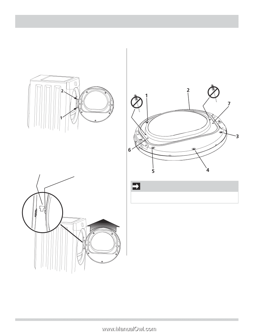
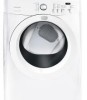
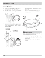
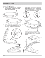
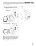
REVERSING DOOR Removing the door 1 Protect flat work surface, such as top of dryer or floor near dryer, with a soft cloth or towel. 2 Open dryer door and remove the two hinge screws. Remove lower screw first, then upper screw. 4 Gently place dryer door face down on flat, covered work surface. 5 Locate the 5 indented head screws (no. 1-5) in the small, circular recesses (at 11, 1, 4, 6, and 8 o'clock positions) of the inner door. Remove and save these 5 screws. 3 Supporting door with both hands, squarely lift door and hinge upward approximately 3/8" (10 mm) so "T" post on back of hinge can slide out through "T" slot on front panel. "T" SLOT IN FRONT PANEL "T" POST ON DOOR HINGE IMPORTANT Do not attempt to remove the 2 "tamper-resistant" screws that hold the inner glass in place. 6 Locate the 2 pan head screws (no. 6-7) on the inner door nearest the metal strike and center of hinge (9 and 3 o'clock positions). Remove and save these 2 screws. 7 Separate inner door assembly from outer door assembly. 18
-
 1
1 -
2
-
3
-
4
-
5
-
6
-
7
-
8
-
9
-
10
-
11
-
12
-
 13
13 -
 14
14 -
 15
15 -
 16
16 -
 17
17 -
 18
18 -
 19
19 -
 20
20 -
 21
21 -
 22
22 -
 23
23 -
24
-
25
-
26
-
27
-
28
-
29
-
30
-
31
-
32
-
33
-
34
-
35
-
36
-
37
-
38
-
39
-
40
-
41
-
42
-
43
-
44
-
45
-
46
-
47
-
48
 |
 |