Frigidaire FCGD3000ES Use and Care Manual - Page 10
Replacing Nylon Timing Cams On Accumulator
 |
UPC - 012505375019
View all Frigidaire FCGD3000ES manuals
Add to My Manuals
Save this manual to your list of manuals |
Page 10 highlights
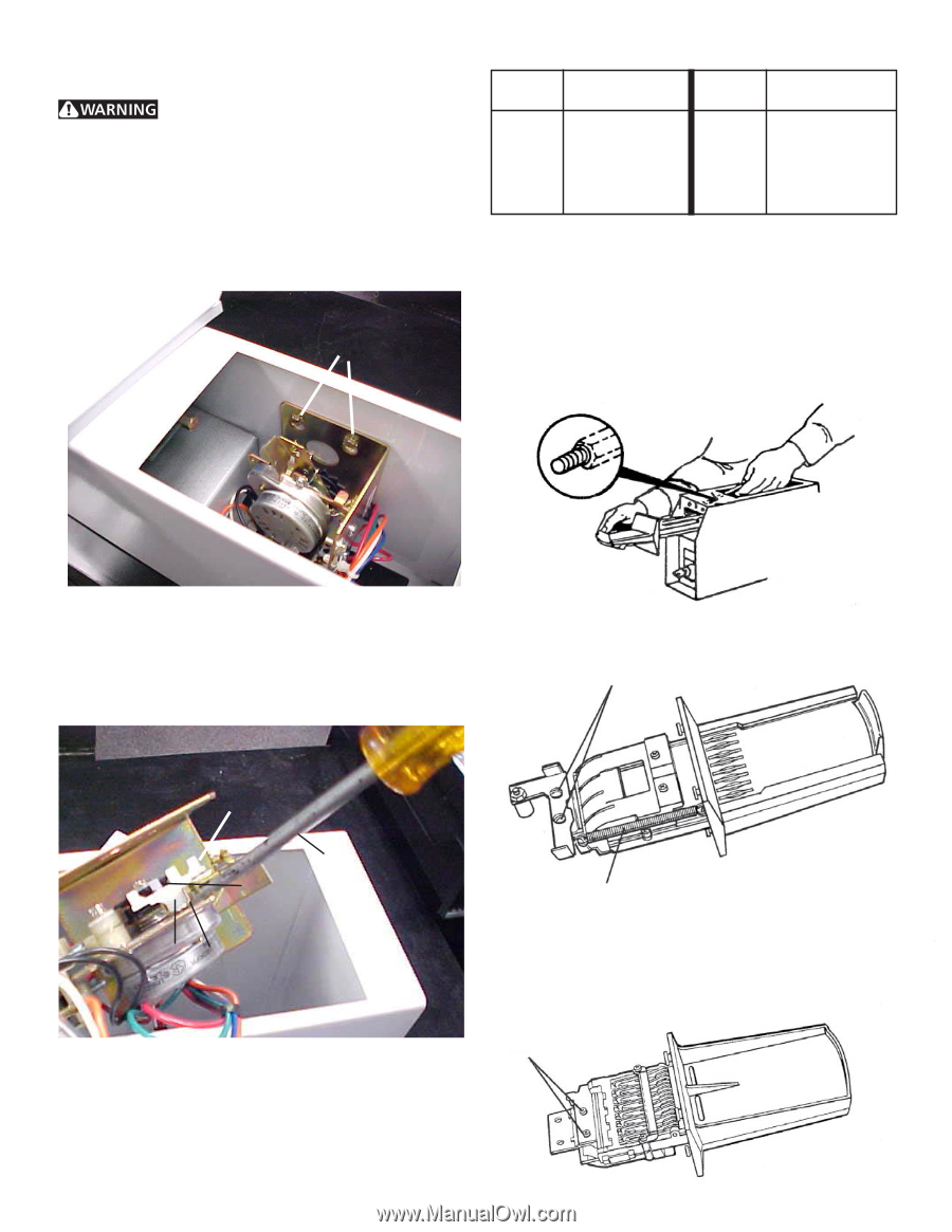
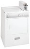
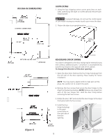
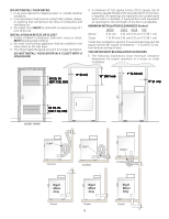
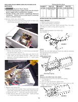
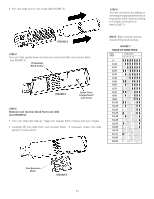
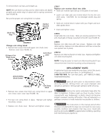
REPLACING NYLON TIMING CAMS ON ACCUMULATOR MECHANISM Electrical Shock Hazard • Disconnect both power supply cords from the electric power supply before making these changes. • Change timing cams before completing electrical connection. Failure to do so could result in electrical shock or personal injury. A. Remove meter-case service door: 1. Loosen two screws securing timer bracket to meter case and lift timer assembly out. See FIG. 2 Screws (2) Timing Cam Pin Chart NUMBER OF PINS 1 2 3 4 5 6 TIME PER COIN INSERTED 180 minutes 90 60 45 36 30 NUMBER OF PINS 7 8 9 10 11 12 TIME PER COIN INSERTED 25.7 22.5 20 18 16.3 15 INSTRUCTIONS FOR CHANGING VEND PRICE TOOLS NEEDED • Medium sized slotted screwdriver • Small slotted Phillips screwdriver Place all screws and other items removed from coin slide assembly on a cloth so they will not get lost. STEP 1 Remove slide mechanism from meter case (see FUGURE 1). FIGURE 2 FIGURE 1 B . Remove nylon timing cam: 1. Rotate cam by hand until "V" notch lines up underneath the ratchet tooth. See FIG. 3. 2. Insert narrow screwdriver under nylon cam close to the timer shaft. Lift cam gently off shaft. Make sure that pressure is directed upward and the "V" notch clears the ratchet tooth. STEP 2 Remove the coin slide extension from coin slide by removing two mounting screws and spacers (see FIGURE 2). (2) Mounting Screws and Spacers Timing Cam FIGURE 2 Lift Line Up Gently Notch with to Clear Narrow Ratchet Blade Hub Drive Tooth Down Lug FIGURE 3 C. Replace new timing cam: 1. Be sure drive lug is in place. Place cam (hub down) over timer shaft, lining up flat on shaft with flat of drive lug hole. 2. Rotate cam until "V" notch lines up with ratchet tooth. 3. Press down to seat cam on timer shaft. make sure that "V" notch freely clears ratchet tooth. Slide Return Spring STEP 3 Remove coin slide from coin chute: • Unhook and remove the coin slide return spring (see FIGURE 2). • Turn coin slide mechanism upside down. • Remove coin slide stop by taking out two screws to the chute bottom (see FIGURE 3). (2) Slide Stop Screws FIGURE 3 10
-
 1
1 -
2
-
3
-
4
-
 5
5 -
 6
6 -
 7
7 -
 8
8 -
 9
9 -
 10
10 -
 11
11 -
 12
12 -
 13
13 -
 14
14 -
 15
15 -
16
 |
 |