Frigidaire FCS366EC Use and Care Guide - Page 8
Before Setting Surface Controls - rating
 |
UPC - 057112090528
View all Frigidaire FCS366EC manuals
Add to My Manuals
Save this manual to your list of manuals |
Page 8 highlights
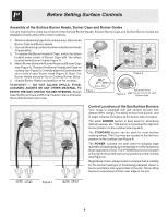
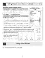
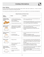
Before Setting Surface Controls Assembly of the Surface Burner Heads, Burner Caps and Burner Grates It is very important to make sure that all of the Surface Burner Heads, Surface Burner Caps and Surface Burner Grates are installed correctly and at the correct locations. 1. Remove all packing tape from cooktop area. Remove all Burner Caps and Burner Heads. 2. Discard all packing material located under Burner Heads (if applicable). 3. To replace the Burner Heads & Caps, match the letters located under center of Burner Caps with the letters located inside Burner Heads (Figure 1). 4. Match Burner Skirts with Burner Heads and Burner Caps (see Figure 1). Replace the Burner Heads and Caps on cooktop (see Figure 2). Carefully align the Electrodes into slot or hole of each Burner Head (Figure 3). Note: The Burner Heads should sit flat on Cooktop Burner Skirts. 5. Unpack Burner Grates and position on the cooktop. REMEMBER - DO NOT ALLOW SPILLS, FOOD, CLEANING AGENTS OR ANY OTHER MATERIAL TO ENTER THE GAS ORIFICE HOLDER OPENING. Always keep the Burner Caps and Burner Heads in place whenever the surface burners are in use. Figure 1 14K or 12K 5K 9.5K 16K Figure 2 Electrodes must Figure 3 align into slot or hole for each Burner Head LEFT REAR LEFT REAR LEFT FRONT LEFT FRONT Figure 4 RIGHT FRONT RIGHT FRONT RIGHT REAR RIGHT REAR Control Locations of the Gas Surface Burners Your range is equipped with gas surface burners with different BTU ratings. The ability to heat food quicker and in larger volumes increases as the burner size increases. The small SIMMER burner is best used for simmering delicate sauces, etc. This burner is located at the right rear burner position on the cooktop (see Figure 4). The STANDARD burner can be used for most surface cooking needs. The 2 burners are located at the left front position on the cooktop (see Figure 4). The POWER burners are best used for bringing large quantities of liquid rapidly up to temperature or when preparing larger quantities of food. The 2 POWER burners are located at the right front and left rear burner positions on the cooktop (see Figure 4). Regardless of size, always select cookware that is suitable for the amount and type of food being prepared. Select a burner and flame size appropriate to the pan. Never allow flames to extend beyond the outer edge of the pan. 8
-
 1
1 -
2
-
 3
3 -
 4
4 -
 5
5 -
 6
6 -
 7
7 -
 8
8 -
 9
9 -
 10
10 -
 11
11 -
 12
12 -
 13
13 -
14
-
15
-
16
-
17
-
18
-
19
-
20
-
21
-
22
-
23
-
24
 |
 |
