Frigidaire FEC26C2AC Installation Instructions (All Languages) - Page 5
Cooktop Installation - parts
 |
UPC - 057112079844
View all Frigidaire FEC26C2AC manuals
Add to My Manuals
Save this manual to your list of manuals |
Page 5 highlights
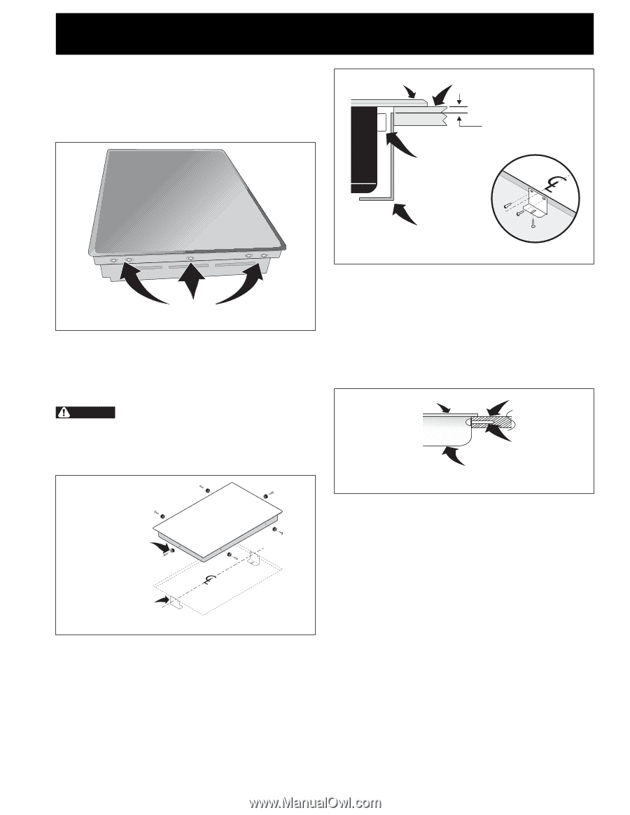
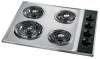
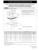
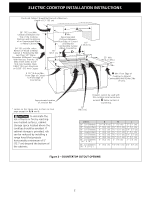
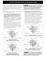
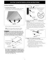
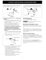
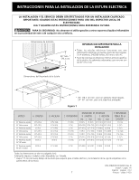
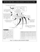
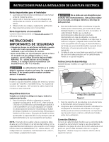
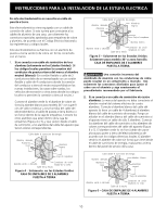
ELECTRIC COOKTOP INSTALLATION INSTRUCTIONS Cooktop Installation 1. All Ceramic-Glass Cooktops Visually inspect the cooktop for damage. Also make sure all cooktop screws are tight (see Figure 8). COOKTOP COUNTERTOP NYLON SPACER Retainer Brackets Must Be Installed At Lest 1/16" (0.16 cm) BELOW Countertop SCREWS Figure 8 Set the cooktop into the countertop cutout. NOTE: Do not use caulking compound; cooktop should be removable for service when needed. WARNING Do not remove the nylon spacers on the edges of the cooktop. These spacers center the cooktop in the space provided. The cooktop must be centered to prevent excess heat buildup that may result in heat damage or fire (see Figure 9). RETAINER BRACKET Figure 10 2. Models: 26" and 36" (36"X18") Coil Elements Cooktops Set the cooktop into the contertop cutout. Lift the cooktop and fasten the ends of the box to the counter with wood screws (figure 11). Lower the cooktop. Align the knobs on the shafts and press down with even pressure. After setting the unit into the opening, all remaining work must be done from inside the cabinet. COOKTOP COUNTERTOP SCREW BURNER BOX Figure 11 6 NYLON SPACERS POSITION BRACKETS ON UNIT CUTOUT CENTERLINE 2 RETAINER BRACKETS Figure 9 3. Models: 32" Coil Elements Cooktops 1. Place cooktop into countertop opening and center unit in cutout. 2. Remove all surface units and drip bowls. 3. Unit clamp down information. Once unit is installed in counter opening, you must clamp unit down as shown in figure 12. 4. Put back all surface units and drip bowls. 5. Make electrical connections as outlined in "Electrical Connection" section. The retainer brackets MUST be installed, to meet local codes or, in their absence, with the National Electrical Code ANSI/NFPA No. 70-latest edition, or with CSA Standard C22.1, Canadian Electrical Code, Part 1 (see Figure 10). 5
-
 1
1 -
 2
2 -
 3
3 -
 4
4 -
 5
5 -
 6
6 -
 7
7 -
 8
8 -
 9
9 -
 10
10 -
 11
11 -
12
-
13
-
14
-
15
-
16
-
17
-
18
-
19
-
20
 |
 |