Frigidaire FFGF3054TS Installation Instructions - Page 7
Checking manifold gas pressure - gas range
 |
View all Frigidaire FFGF3054TS manuals
Add to My Manuals
Save this manual to your list of manuals |
Page 7 highlights
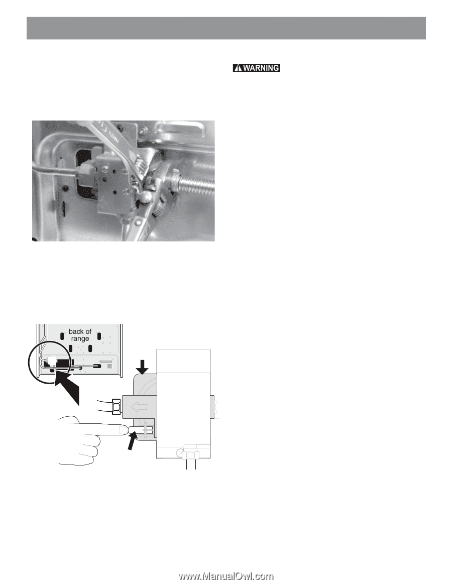
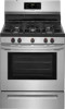
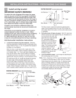
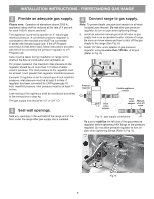
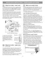
INSTALLATION INSTRUCTIONS - FREESTANDING GAS RANGE c. Tighten the gas supply fitting and/or appliance conduit to flare union adaptor on the right side of the pressure regulator (refer to Fig. 10) using NO MORE THAN 15ft./lbs. of torque. Be sure to stabilize the 1/2" flare union adapter with an adjustable wrench before tightening the gas supply fitting and/or appliance conduit. Fig. 10 d. Install flare union adapter to external manual shut-off valve (See Fig. 8). e. Attach flexible appliance conduit to flare union adaptor on shut-off valve (See Fig. 8). f. Make sure the service shut-off valve on pressure regulator is set to the ON position (See Fig. 11). Checking manifold gas pressure Do not use flame to check for gas leaks. Disconnect the range and its individual shut-off valve from the gas supply piping system during any pressure testing of that system at test pressures greater than 14" of water column pressure (approximately 1/2" psig). The appliance must be isolated from the gas supply piping system by closing its individual manual shut-off valve during any pressure testing of the gas supply piping system at test pressures equal to or less than 14" of water column pressure (approximately 1/2" psig). If it should be necessary to check the manifold gas pressure, connect manometer (water gauge) or other pressure device to the top burner right rear orifice. Using a rubber hose with inside diameter of approximately 1/4," hold tubing down tight over orifice. Turn burner valve on. For an accurate pressure check have at least two (2) other top burners burning. Be sure the gas supply (inlet) pressure is at least one inch above specified range manifold pressure. The gas supply pressure should never be over 14" water column. When properly adjusted for Natural Gas the manifold pressure is 4". For LP/Propane Gas the manifold pressure is 10". Pressure regulator Service shut-off valve (shown in ON position) Fig. 11 g. Check for gas leaks. Turn the gas supply on to the range and use a liquid leak detector at all joints and conduits to check for leaks in the system. 7
-
 1
1 -
 2
2 -
 3
3 -
 4
4 -
 5
5 -
 6
6 -
 7
7 -
 8
8 -
 9
9 -
 10
10 -
 11
11 -
 12
12 -
13
-
14
-
15
-
16
-
17
-
18
-
19
-
20
-
21
-
22
-
23
-
24
-
25
-
26
-
27
-
28
-
29
-
30
-
31
-
32
 |
 |