Frigidaire FFHB2750TP Wiring Diagram - Page 1
Frigidaire FFHB2750TP Manual
 |
View all Frigidaire FFHB2750TP manuals
Add to My Manuals
Save this manual to your list of manuals |
Page 1 highlights
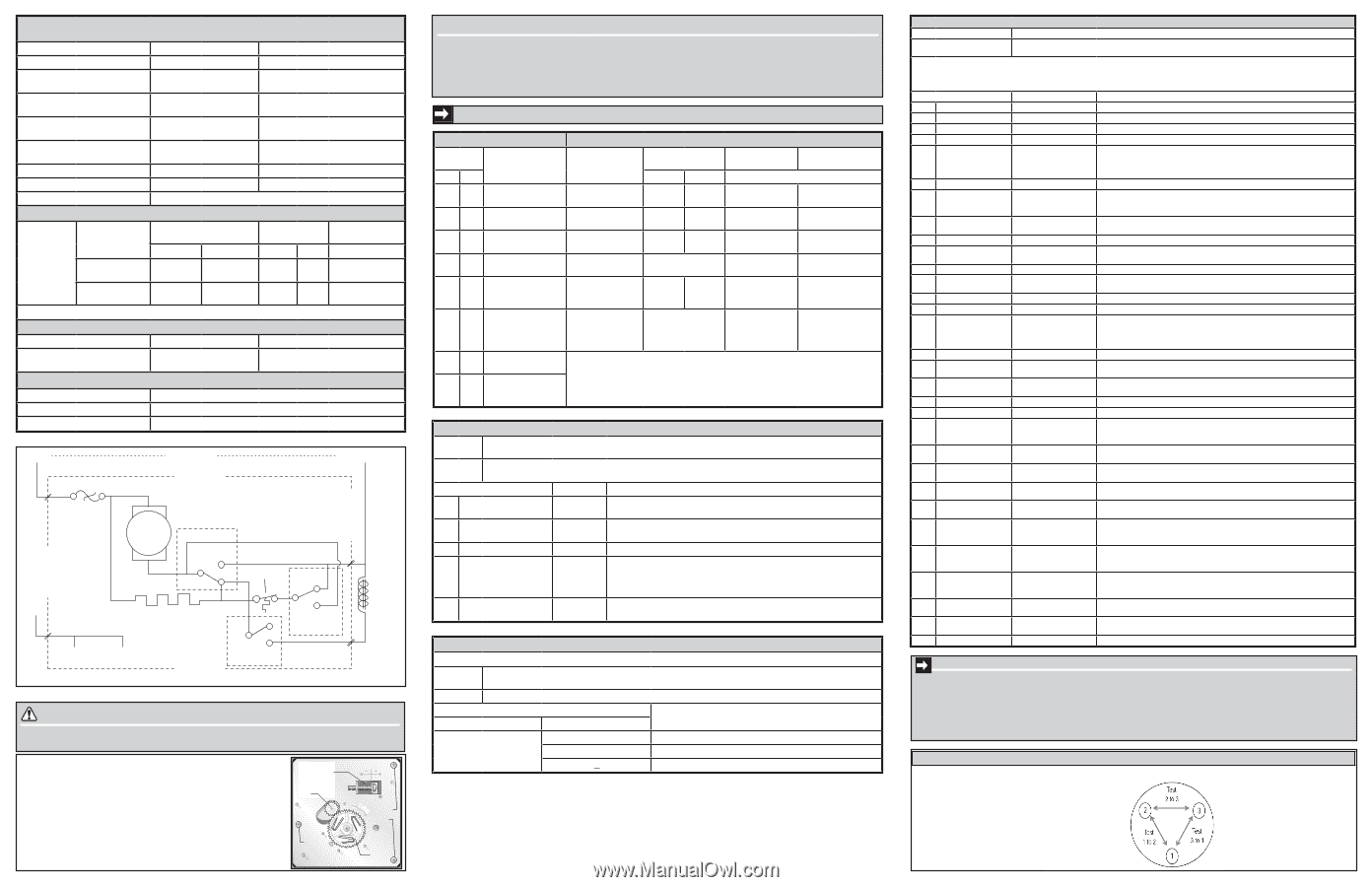
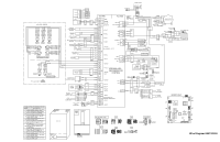
PERFORMANCE DATA NO LOAD & NO DOOR OPENINGS AT 37°/0° CONTROL SETTING Type A with Run / Start Capacitor 65°F (18°C) Ambient 90°F (32°C) Ambient Operating Time 90 to 100% 100% Freezer Temperature -5° to 2°F (-20° to -17°C) -1° to 3°F (-18° to -16°C) Refrigerator Temperature Low Side Pressure High Side Pressure (last 1/3 cycle) Wattage (last 1/3 cycle) 34° to 39°F (1° to 4°C) -2 to 6 psig (-14 to 41 kPa) 85 to 105 psig (586 to 724 kPa) 30 to 50 34° to 39°F (1° to 4°C) -2 to 6 psig (-14 to 41 kPa) 120 to 135 psig (827 to 931 kPa) 50 to 70 Amps (running) .4 to .8 .7 to .9 Base Voltage 115 vac (127 vac max) DEFROST SPECIFICATIONS Cabinet Size: Thermal Cutout Cut-in Cut-out Heater Watts Ohms Defrost Thermistor Termination Cut-out 27' & 28' SD, 22' CD Freezer Fresh Food Ice Maker 110°F (43.3°C) 110°F (43.3°C) 135°F (57.2°C) 135°F (57.2°C) 500 26.5 70 188.9 Electronic Timer - (ADC) Defrost 24 minutes every 6-96 hours of compressor run time. CONDENSER FAN MOTOR 48°F (8°C) 68°F (20°C) Watts RPM Amps 3.1 1100 CW Opposite Shaft 0.03 Running FREEZER ICE MAKER SPECIFICATIONS Electrical Thermostat 115 vac (127 vac max) Opens at 48°F ( 9°C), Closes at 15° F ( -9°C) Heater Voltage 115 vac LINE POWER NEUTRAL ICE MAKER LT. BLUE ICE MAKER BLK BRN P-3 THERMAL CUT-OUT WATER VALVE ICE MAKER BLK RED MOTOR RED HOLD SWITCH NO LT. BLUE RED C NC THERMOSTAT P-4 NO BLK BLU NC C MOLD HEATER 165 WATTS SHUTOFF NO SWITCH GRN / YEL P-1 MOLD MOUNTING PLATE ICE MAKER NC C WATER FILL SWITCH YELLOW P-2 CAUTION All electrical parts and wiring must be shielded from torch flame. DO NOT allow torch to touch insulation; it will char at 200°F and flash ignite (burn) at 500°F. Excessive heat will distort the plastic liner. FREEZER ICE MAKER INFORMATION (Where Applicable) Test Cycling: Remove cover by inserting screwdriver in notch at bottom and prying cover from housing. Use screwdriver to rotate motor gear counterclockwise until holding switch circuit is completed. All components of ice maker should function to complete the cycle. Water Fill Volume: The water fill adjustment screw will change the fill time. One full turn is equal to 20cc (.68 oz.). The correct fill is 102 to 130cc (3.4 to 4.3 oz.). When a water valve is replaced, the fill volume must be checked. Water Fill Adjustment Motor Gear Mounting Plate Screw N TUR Mounting Plate Screws Timing Gear SERVICE DATA SHEET A06589001 Activate: Deactivate: SYSTEM DIAGNOSTIC MODE Press ^ and v for up to 10 sec. simultaneously. Press + to advance through tests. Press + for up to 10 sec. Diagnostic Mode will automatically deactivate after 5 min. of inactivity. Note: Silence alarm. ICE & WATER - AUTOMATIC DEFROST BOTTOM FREEZER - R134a • Tests marked with "*" may not be applicable to this unit and will not be displayed in System Diagnostic Mode. • Tests displayed in diagnostic mode but not described below are for internal purposes only; advance through. • View UI display for "on," "off," "CL," "OP," "SH," "LO," "HI" or numerical results of tests. • Listen for operating sounds; feel for heat or air flow as appropriate to determine results of tests. Test To activate test: Passing result IMPORTANT: PLEASE RETURN THIS SHEET TO ITS ORIGINAL LOCATION. -- First Screen -- Second Screen -- All LEDs on UI illuminated, except digit displays. -- All segments of UI digit displays illuminated. -- Third Screen -- Blank UI display, no LEDs illuminated. ERROR CODES SPECIAL MODES 28 Dispenser Paddle Press disp. paddle "On" on UI when depressed; "off" when released Display FZ FF -- OP OP --- SH SH -- Interpretation Open FF Cavity Thermistor Open FZ Cavity Thermistor Shorted FF Cavity Thermistor Shorted FZ Cavity Thermistor Mode Manual Defrost Display FZ FF d F Activate Deactivate (press for up to 10 sec. simultaneously) + and - Same to deactivate Demo / Showroom 77 77 Sabbath Sb Sb ^ and v and - Unplug to deactivate Same to deactivate System Diagnostic No FF or FZ display, all UI LEDs on ^ and v Press and hold + to deactivate 46 Humidity Sensor Activates automatically "OP" if open, "SH" if short. AC Heater System: Displays %RH. DC Heater System: "HI" - heater should be on. "Lo" - heater should be off. %RH is displayed when humidity is between "Lo" and "HI" values; heater could be on or off. 47 Dispenser Pocket Heater Press set Heater on when "on' off when "off". 2 Freezer Defrost Heater Press set Freezer defrost heater on when "on"; off when "off". Evaporator thermistor temperature is flashed. Watch for temp increase with the heater on. It may take a few minutes for the evaporator to heat up. 8 Water Valve (Dispenser) Press set FF door must be closed. Be prepared to collect water at dispenser. Water dispenses when "on"; stops when "off" 10 Auger Motor Press set FF door must be closed. Motor running when "on"; motor stopped when "off" 11 Cube/Crush Solenoid Press set FF door must be closed. Do not leave solenoid in activated state. Solenoid activated when "on"; deactivated when "off". 12 Condenser Fan Press set Fan running when "on"; stopped when "off" SY CF UI to Main Board Current Air Temps FZ Temp FF Temp communication failure; on start up SY CE UI to Main Board FFIM Diagnostic Numerical display of communication first test error; after a period in operation v and + and Water ^ and + Automatically after 10 sec Press and hold + to deactivate 43 Mullion Anticonden- Press set sation Heater 38 VCC Compressor Press set 13 FF Lights Press set 15 Freezer Evaporator Fan Press set Flip mullion heater on when "on"; off when "off" Compressor running when "on"; off when "off" FF lights on when "on"; off when "off" Press to toggle between "off", "LO" and "HI". A current sensor reading is flashed (units are not mA). OFF reading should be around 2. "LO" speed reading should settle down to around 9. "HI" speed reading should settle down above 40. SY EF Freezer Evaporator Notes: Fan Failure • Always check for pin back-outs, pinched or damaged wires before replacing components. dl SP Ice Chute Door is open; check for obstruction • Determine whether failure is caused by the component, main control board or wiring. Contact TID before replacing main control board. • Refer to Service Manual for additional information. 20 FZ Lights 22 Damper 36 Ice Chute Door 23 FF Door Press set Press set Depress ice chute door or press set Open/Close FF door FZ lights on when "on", off when "off" Perform test 15 and set fan to "HI". Then check for air flow when open "OP"; and no air leaks when closed "CL" "OP" on UI when manually opened; "CL" when closed . Or using "power on-off", motor drive door open "OP" or closed "CL" "CL" on UI when door closed; "OP" when open 24 FZ Door Open/Close FZ door "CL" on UI when door closed; "OP" when open FRESH FOOD ICE MAKER DIAGNOSTIC MODE Activate: Press ^ and + temperature pads for up to 10 sec. simultaneously. Press + or - to move forward or backward through tests. Deactivate: Press + for up to 10 sec. FFIM Diagnostic Mode will automatically deactivate after 5 min. of inactivity. NOTE: Silence alarm. 26 Ice Maker Defrost Heater 29 FF Thermistor 30 FZ Thermistor Activates automatically Activates automatically Activates automatically Heater is turned on automatically. The ice maker evaporator thermistor temperature is flashed. Watch for temp increase with the heater on. It may take a few minutes for the evaporator to heat up. UI shows temperature sensed by FF thermistor; pass if within 10°F of temperature measured with gauge at FF thermistor location. "OP" if open; "SH" if short UI shows temperature sensed by FZ thermistor; pass if within 10°F of temperature measured with gauge at FZ thermistor location."OP" if open; "SH" if short Test 52C Ice Maker Thermistor To activate test Passing Result Activates FZ display shows temperature sensed by Ice Maker Thermistor. automatically "OP" if open; "SH" if short 33 Ambient Thermistor Activates automatically UI shows temperature sensed at main board; pass if within +20°F/-10°F of tem- @ Main Board perature measured with gauge at main board location. "OP" if open; "SH" if short 34 Ambient Thermistor Activates automatically UI shows temperature sensed at UI; Pass if within +20˚F/-10˚F of tem- @ UI perature measure with gauge at UI location. "OP" if open; "SH" if short. 55C Water Valve Press set Remove ice tray to collect water into a measuring container to measure water fill. If collecting water into ice tray, first perform test 63C to empty ice tray. 39 Freezer Evaporator Activates automatically UI shows temperature sensed by freezer evaporator thermistor; pass if Thermistor within 10°F of temperature measured with gauge at evaporator thermistor location."OP" if open; "SH" if short 57C Evaporator Fan (FFIM) Press set "On" on FZ display when fan activated, "OFF" when deactivated. 45 Ice Maker Mold Activates automatically UI shows temperature sensed at ice maker; pass if within +20°F/-10°F of Ice Level Sensor 58C Activates Remove ice bucket. automatically Allow bail arm to drop freely. Pass if no alarm when tray returns to "home" position. Hold bail arm up. Pass if alarm sounds when tray returns to "home" position. Thermistor temperature measured with gauge at ice maker mold. "OP" if open; "SH" if short 68 Ice Maker Activates automatically UI shows temperature sensed by evaporator thermistor; pass if within 10°F Evaporator Thermistor of temperature measured with gauge at evaporator thermistor location. This test runs continuously until another test is selected. "OP¯" if open; "SH¯" if short 63C Twist Tray Press set Remove ice bucket. → Check at the connector from the power cord harness into the inverter board, located in FZ display shows "1" andth"eGmOaOchDin".e compartment. (PUR and WHT wires) → Check at Inverter Bo0a-rd onFirmware Param- → RemPorevessinsveetrter box from the Displays digit→seCqhueceknccoen;nreecctoiornds from Inverter Compressor eters compressor and check resistance Board to Compressor yes (BLK and RED wires) 1- Main Board Fyirems - Is Inverter Board receivwinagre10-15 across compressor shoPwrne.ss set winding pairsDaissplaysydeisgit seAqreuecnocnen;ercetcioonrds from Board to Compressor Inverter intact? Is Inverter Board receiving 115 VAC FRESH FOOD ICE MAKER FILL TIME AfrDomJUpSowTeMr EsuNpTplyM? ODE VAC and 1-5 VDC3f-romUMIaFiinrmware Control Board? Is rPerseisstsasnecte across all windiDnigsplays digit sequence; record pairs equal? Activate: NOTE: First consider water filter condition before adjustinnog fill time. Press and hold the Water and Crush pads for up to 10 seconds. Press + or - to adjust between the 3 fill settings. Deactivate: Exits automatically after 10 seconds, or press any button other th•anCh+ecokrvo-.ltage supply. Display FZ FF • Check and repair power cord harness wiring and connecDtioenss.cription − Min Fill Time (default) IC = Mid Fill Time = Max Fill Time no IMPORTANT SAFETYno NOTE no The not this information provided RheeprlaecienCiosmdpreessisgornaendd to assist attempt to make repaIinrvserdteur eBotaord.the possibility of appliance. qualified repair personnel only. Untrained persons should electricalIdsehnotifcyka.ndDriespcaoirndnaemcatgepdower cord before servicing wires or poor connections between Inverter Board and → Check at Main ConItrMol PBoOarRd TANT Compressor. (BLK/WHT and RED/BILfKawniryes)green grounnoding wires are removed during servicing, they must be returned to theyeirs original position and Is Main Control Bporoarpdesrelyndsiencgured. Replace Main Control Board. 10-15 VAC and 1-5 VDC to Inverter Board? yes VCC CVCOCMRePsRisEtaSnSceOCRheMckOTOR RESISTANRCepElacCeHInEveCrtKer Board Check resistance between terminals 1 and Identify and repair damaged wires or poor connections between Main Control Board and Inverter Board. 2, 2 and 3, 3 and 1. If all resistances are equal, compressor is operative.
-
 1
1 -
 2
2
 |
 |