Frigidaire FFVU17F4QW Wiring Diagram - Page 1
Frigidaire FFVU17F4QW Manual
 |
View all Frigidaire FFVU17F4QW manuals
Add to My Manuals
Save this manual to your list of manuals |
Page 1 highlights
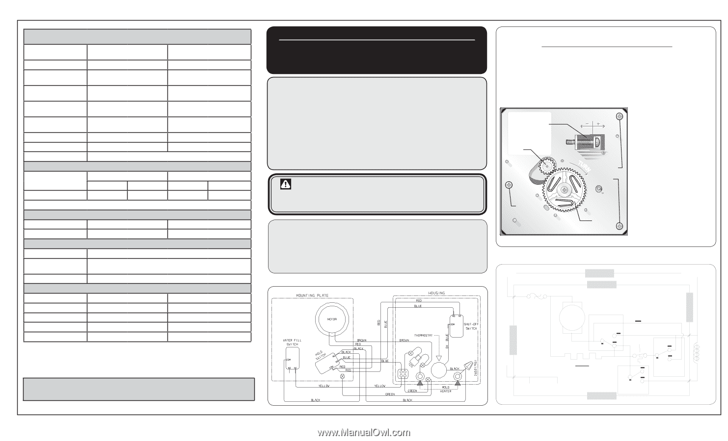
PERFORMANCE DATA NO LOAD & NO DOOR OPENINGS AT MID-POINT CONTROL SETTING Capacitor Run or Induction Run 70°F (21°C) Ambient 90°F (32°C) Ambient Operating Time 40 to 50% 55 to 65% Freezer Temperature -3° to 3° F -19° to -16° C -3° to 3° F -19° to -16° C Low Side Pressure (cut-in) 6 to 12 psig 41 to 83 kPa 6 to 12 psig 41 to 83 kPa Low Side Pressure (cut-out) -1 to 3 psig -4 to 21 kPa -1 to 3 psig -4 to 21 kPa High Side Pressure (last 1/3 cycle) 85 to 100 psig 575 to 670 kPa 120 to 135 psig 810 to 910 kPa Wattage (last 1/3 cycle) 100 to 120 110 to 130 Amps (running) .9 to 1.1 1.0 to 1.2 Base Voltage 115 vac (127 vac max) DEFROST SPECIFICATIONS Cabinet Size Thermostat Cut-in Cut-out Heater Watts Ohms 19' 21° F (-6° C) 42° F (6° C) 550 24 Electronic Timer - Defrost 30 minutes every 12 hours of compressor run time. CONDENSER FAN MOTOR Watts RPM Amps 2.3 1100 CW Opposite Shaft 0.13 Running ICE MAKER SPECIFICATIONS Electrical 115 vac (127 vac max) 60 Hertz Thermostat Opens at 48° F ( 9° C), Closes at 15° F ( -9° C) Models with orange wire close at 8.96° F (-12.8° C) Heater Wattage 165 ICE MAKER CONNECTOR PLUG CONNECTIONS Wire Number Wire Color Connects to: 1 Green/Yellow Ground 2 Yellow Water Valve 3 Black Line 4 Light Blue Neutral IMPORTANT: PLEASE RETURN THIS SHEET TO IT'S ORIGINAL LOCATION service data sheet - 297299800 STANDARD - AUTOMATIC DEFROST FREEZER MODELS (r134a) important safety notice The information provided herein is designed to assist qualified repair personnel only. Untrained persons should not attempt to make repairs due to the possibility of electrical shock. Disconnect power cord before servicing. important If any green grounding wires are moved during servicing, they must be returned to their original position and properly secured. caution: All electrical parts and wiring must be shielded from torch flame. Do not allow torch to contact insulation; it will char at 200°F. NOTE: Products come equipped with an Electronic Defrost Control. To initiate defrost, press and hold air filter and alarm reset key simultainiously for three seconds. To terminate defrost, press and hold air filter and alarm reset key simultainiously for three seconds iCE MAKER INFORMATION Test Cycling Remove cover by inserting screwdriver in notch at bottom and prying cover from housing. Use screwdriver to rotate motor gear counterclockwise until holding switch circuit is completed. All components of ice maker should function to complete the cycle. Water Fill Adjustment Motor Gear Mounting Plate Screw TUR Mounting N Plate Screws Water Fill Volume The water fill adjustment screw will change the fill time. One full turn is equal to 20cc (.68 oz.). The correct fill is 95 to 105cc (3.2 to 3.6 oz.). When a water valve is replaced, the fill volume must be checked. Timing Gear LINE BLK B LK P-3 THER MAL CUT-OUT BLK POWER ICE MA KER BRN MOTOR RED HO LD SW ITCH YEL T HERMOSTAT ICE MAKER YEL NEUT RAL P-4 YEL RED ICE MAKER WATER VALVE LT. BLU GRN / yEL BLK BLU MOLD HEATER GRN / yEL P-1 MOL D MOUN TING PLATE SHUT-OF F SWITCH LT. BLU P-2 WATER FILL S WITCH ICE MAKER
-
 1
1 -
 2
2
 |
 |