Frigidaire FGGF3047TF Installation Instructions - Page 10
Make sure range is level., Adjust air shutter - lower oven., Adjust air shutter - upper oven.
 |
View all Frigidaire FGGF3047TF manuals
Add to My Manuals
Save this manual to your list of manuals |
Page 10 highlights
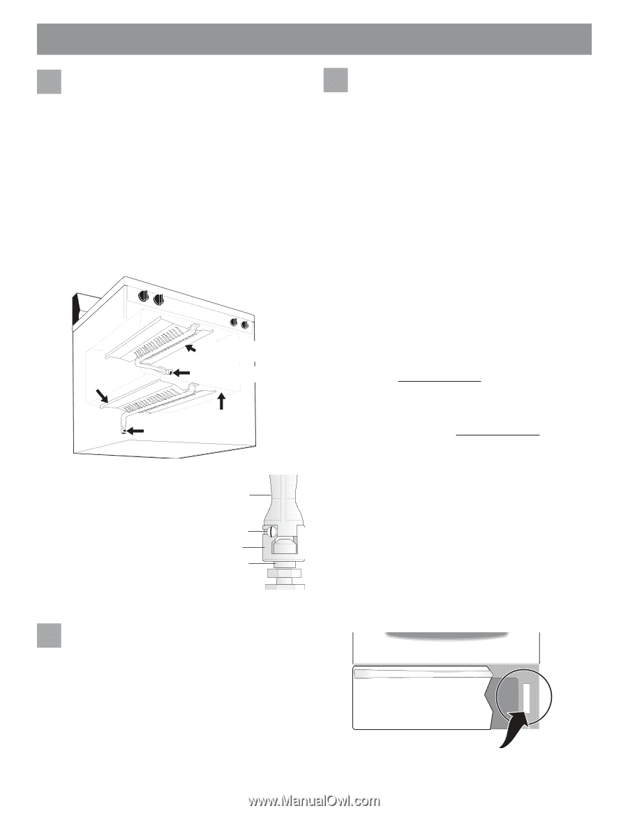
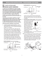
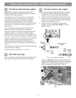
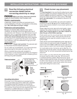
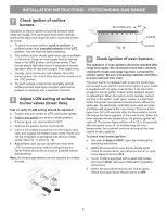
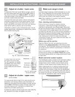
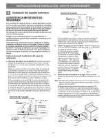
INSTALLATION INSTRUCTIONS - FREESTANDING GAS RANGE 10 Adjust air shutter - lower oven. To determine if the oven burner flame is proper, remove the oven bottom panel and lower burner baffle (Refer to Fig. 19) and set the oven to Bake at 300°F. The approximate flame length of the lower oven burner should be 1 inch with a distinct inner blue flame. To remove the lower oven bottom, remove oven bottom hold down screws at rear of oven bottom panel. Pull up at rear, disengage front of oven bottom from oven front frame, and pull the oven bottom out of the oven. Remove lower burner baffle to observe oven burner flame. If the flame is yellow in color, increase the lower oven air shutter opening size. If the flame is a distinct blue, reduce the air shutter opening size. Lower oven burner baffle (removable) Upper oven burner (some models) Upper oven burner air shutter (some models) Lower oven burner air shutter Lower oven bottom panel (removable) Fig. 19 - oven burner locations To adjust lower oven air shutter loosen lock screw (See Fig. 20), reposition air shutter, and tighten lock screw. When finished adjusting replace burner baffle and oven bottom panel. Oven burner Lock screw Air shutter Orifice hood Fig. 20 - typical oven burner air shutter 11 Adjust air shutter - upper oven. (some models). 12 Make sure range is level. Level the range by placing a level horizontally on an oven rack. Check diagonally from front to back, then level the range by either adjusting the leveling legs or by placing shims under the corners of the range as needed. Note: After installation is complete, make sure all controls are left in the off position. Care, cleaning and maintenance Refer to the User's manual for detailed cleaning instructions. If removing the range is necessary for cleaning or maintenance, shut off gas supply. Disconnect the gas and electrical supply. If the gas or electrical supply is inaccessible, lift the range slightly at the front and pull out away from the wall. Pull out only as far as necessary to disconnect the gas and electrical supply. Finish removing the range for servicing and cleaning. Reinstall in reverse order making sure to level the range and check gas connections for leaks. Be sure to read and follow step 1 for proper Anti-tip installation. Before you call for service Read the "Before You Call" and operating instruction sections in your Use & Care Guide. It may save you time and expense. The list includes common occurrences that are not the result of defective workmanship or materials in this appliance. Refer to the warranty in your Use & Care Guide for our toll-free service number and address. Please call or write if you have inquiries about your range product and/or need to order parts. Model and serial number location The identification plate is located on the right-hand surface of the oven front frame. To access this plate, open the storage drawer (some models), warmer drawer (some models) or broiler drawer (some models) (See Fig. 21). When ordering parts for or making inquires about your range, always be sure to include the model and serial numbers and a lot number or letter from the identification plate on your range. Your identification plate also tells you the rating of the burners, the type of fuel and the pressure the range was adjusted for when it left the factory. The approximate flame length of the upper (broil) burner should be 1 inch having a distinct inner, blue flame. To determine if the upper broil burner flame is proper, set the oven to Broil. If the flame is yellow, increase upper oven air shutter opening size. If the flame is a distinct blue, reduce the air shutter opening size. To adjust the upper air shutter loosen lock screw (See Fig. 20), reposition air shutter, and tighten lock screw. Fig. 21 10
-
 1
1 -
2
-
3
-
4
-
 5
5 -
 6
6 -
 7
7 -
 8
8 -
 9
9 -
 10
10 -
 11
11 -
 12
12 -
 13
13 -
 14
14 -
 15
15 -
16
-
17
-
18
-
19
-
20
 |
 |