Frigidaire FGGF3685TS Wiring Diagram - Page 1
Frigidaire FGGF3685TS Manual
 |
View all Frigidaire FGGF3685TS manuals
Add to My Manuals
Save this manual to your list of manuals |
Page 1 highlights
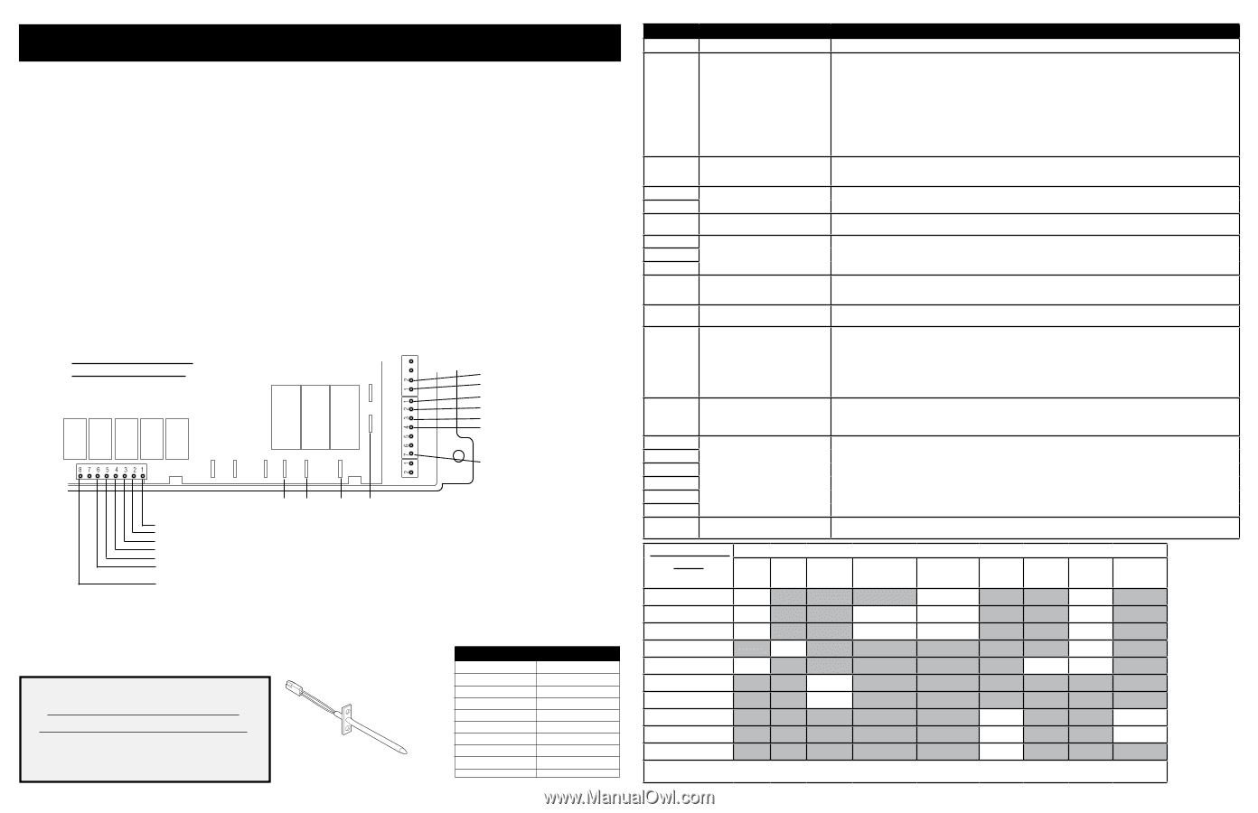
SERVICE DATA SHEET Gas Range with ES 536/586 Electronic Oven Control NOTICE - This service data sheet is intended for use by persons having electrical and mechanical training and a level of knowledge of these subjects generally considered acceptable in the appliance repair trade. The manufacturer cannot be responsible, nor assume any liability for injury or damage of any kind arising from the use of this data sheet. SAFE SERVICING PRACTICES To avoid the possibility of personal injury and/or property damage, it is important that safe servicing practices be observed. The following are examples, but without limitation, of such practices. 1. Before servicing or moving an appliance remove power cord from electrical outlet, trip circuit breaker to OFF, or remove fuse. 2. Never interfere with the proper installation of any safety device. 3. GROUNDING: The standard color coding for safety ground wires is GREEN or GREEN WITH YELLOW STRIPES. Ground leads are not to be used as current carrying conductors. It is extremely important that the service technician reestablish all safety grounds prior to completion of service. Failure to do so will create a potential safety hazard. 4. Prior to returning the product to service, ensure that: • All electric connections are correct and secure. • All electrical leads are properly dressed and secured away from sharp edges, high-temperature components, and moving parts. • All uninsulated electrical terminals, connectors, heaters, etc. are adequately spaced away from all metal parts and panels. • All safety grounds (both internal and external) are correctly and securely reassembled. Oven Calibration Set the electronic oven control for normal baking at 350°F. Obtain an average oven temperature after a minimum of 5 cycles. Press STOP or CLEAR keypad to end Bake mode. Temperature Offset Adjustment See Owner's Manual Note: Changing calibration affects all Baking modes. The adjustments made will not change the self-cleaning temperature. Electronic Oven Control & jumper connections (EOC rear view) P5 L2 IN L2 OUT J3 P3 P1 P11 P9 P7 CONV BAKE BROIL L1 COOLING FAN MOTOR - HIGH COOLING FAN MOTOR - LOW OVEN LIGHT MOTOR DOOR LATCH CONVECTION FAN L1 N P8 P11 P12 MEAT PROBE MEAT PROBE TEMP PROBE TEMP PROBE EXTERNAL SWITCH RETURN DOOR SWITCH MOTOR DOOR LATCH SWITCH IMPORTANT DO NOT REMOVE THIS BAG OR DESTROY THE CONTENTS WIRING DIAGRAMS AND SERVICE INFORMATION ENCLOSED REPLACE CONTENTS IN BAG p/n 809008409 Rev A (1701) ENGLISH Resistance Temperature Detector RTD SCALE Temperature °F (°C) Resistance (ohms) 32 ± 1.9 (0 ± 1.0) 1000 ± 4.0 75 ± 2.5 (24 ± 1.3) 1091 ± 5.3 250 ± 4.4 (121 ± 2.4) 1453 ± 8.9 350 ± 5.4 (177 ± 3.0) 1654 ± 10.8 450 ± 6.9 (232 ± 3.8) 1852 ± 13.5 550 ± 8.2 (288 ± 4.5) 2047 ± 15.8 650 ± 9.6 (343 ± 5.3) 2237 ± 18.5 900 ± 13.6 (482 ±7.5) 2697 ± 24.4 Probe circuit to case ground Open circuit/infinite resistance Fault Code F10 F11 F12 F13 F15 F16 F17 F18 F30 F31 F33 F60 F90 F91 F92 F93 F94 F95 Line ERR ELECTRONIC OVEN CONTROL (EOC) FAULT CODE DESCRIPTIONS Likely Failure/Cause Suggested Corrective Action Runaway Temperature. Oven heats when no cook cycle is programmed. If Oven is cold: 1. If fault code is present with cold oven test oven temperature sensor probe circuit resistance. Use RTD scale found in the tech sheet. 2. Replace probe or repair wiring connections if defective. 3. If temperature sensor probe circuit is good but fault code remains when oven is cold replace the EOC. If Oven is overheating: 1. If oven is severely overheating/heating when no cook cycle is programmed test oven temperature sensor probe circuit resistance using the RTD scale found in the service tech sheet. Also verify that the temperature sensor probe in properly installed in the oven cavity. 2. Disconnect power from the range, wait 30 seconds and reapply power. If oven continues to heat when the power is reapplied, replace the EOC. NOTE: Severe overheating may require the entire oven to be replaced should damage be extensive. Shorted keypad or Selector Switch. 1. Reset power supply to range - Disconnect power, wait 30 seconds and reapply power. 2. Check/reseat ribbon harness connections. 3. Replace the EOC. EOC internal software error or failure Disconnect power, wait 30 seconds and reapply power. If fault returns upon power-up, replace EOC. (some models). EOC internal hardware error or failure (some models). EOC internal software error or failure (some models). Disconnect power, wait 30 seconds and reapply power. If fault returns upon power-up, replace EOC. Disconnect power, wait 30 seconds and reapply power. If fault returns upon power-up, replace EOC. Open oven sensor probe circuit. Shorted oven sensor probe circuit. Meat probe temperature sensor shorted or too hot. Electronic Oven Control (EOC) over temperature. Higher than normal temperature detected on the EOC circuit board. Door lock motor or latch circuit failure. EOC Internal voltage test error or failure. Check resistance at room temperature & compare to RTD Sensor resistance chart. If resistance is correct replace the EOC. If resistance does not match the RTD chart replace RTD Sensor Probe. Check Sensor wiring harness between EOC & Sensor Probe connector. Check resistance at room temperature, if less than 500 ohms, replace RTD Sensor Probe. Check for shorted Sensor Probe harness between EOC & Probe connector. If resistance is correct replace the EOC. 1. The error is triggered if the meat probe sees a temperature in excess of 392°F. Make sure the meat probe was not used in such way that it could have seen such temperature. If the tip of the probe is not inserted in the meat it will see the cavity temperature, which can be higher than 392°F (depending on the setpoint) and trigger the alarm. 2. When the meat probe is connected to the socket inside the oven cavity, if the meat probe is not fully inserted into the socket it may short the contacts and cause the error. Make sure the probe is inserted as much as it can. 3. Verify meat probe resistance at room temperature. Compare to meat probe resistance chart. If the meat probe does not match the chart, replace it. 4. If the above steps failed to correct the problem, replace the oven relay board. 1. Verify proper assembly of backguard panel. Check for damaged or loose panels, brackets, endcaps, etc. 2. Check for blocked ventilation slots in control panel rear cover. 3. Inspect oven vent for proper assembly and air flow. 4. Verify operation of cooling fan (if present). If lock motor runs: 1. Test continuity of wiring between EOC and lock switch on lock motor assy. Repair if needed. 2. Advance motor until cam depresses the plunger on lock motor switch. Test continuity of switch contacts. If switch is open replace lock motor assy. 3. If motor runs and switch contacts and wiring harness test good, replace the EOC. If lock motor does not run: 1. Test continuity of lock motor windings. Replace lock motor assembly if windings are open. 2. Test lock motor operation by using a test cord to apply voltage. If motor does not operate replace lock motor assy. 3. If motor runs with test cord check continuity of wire harness to lock motor terminals. If harness is good replace the EOC. Disconnect power, wait 30 seconds and reapply power. If fault returns upon power-up, replace EOC. Circuit Analysis Matrix L1 to Bake P9 L1 to Broil P7 L1 to Motor Door Latch J3-4 EOC Relays 570 Gas L1 to Convection L1 to Convection L1 to Oven Fan Heating Element Lamps J3-5 P11 J3-3 Cooling fan high J3-1 Cooling fan low J3-2 Door Switch Contacts COM-NO Bake X² X¹ x Convection Bake X² x* X² x Convection Roast X² x* X¹ x Broil x x Self-Clean X x³ x Locking x Unlocking x Door Open x o Door Closed o x Oven Lamps(ON) x Notes: X = Circuit contact closed. O = Circuit contacts open. X¹ = During preheat. X² = Cycles as needed. X³=Temperature dependant. x*= Fan comes on after 6 minutes.
-
 1
1 -
 2
2
 |
 |