Frigidaire FGGH3047VD Installation Instructions - Page 7
Provide an adequate gas, supply., Seal wall openings., Connect range to gas - lp kit
 |
View all Frigidaire FGGH3047VD manuals
Add to My Manuals
Save this manual to your list of manuals |
Page 7 highlights
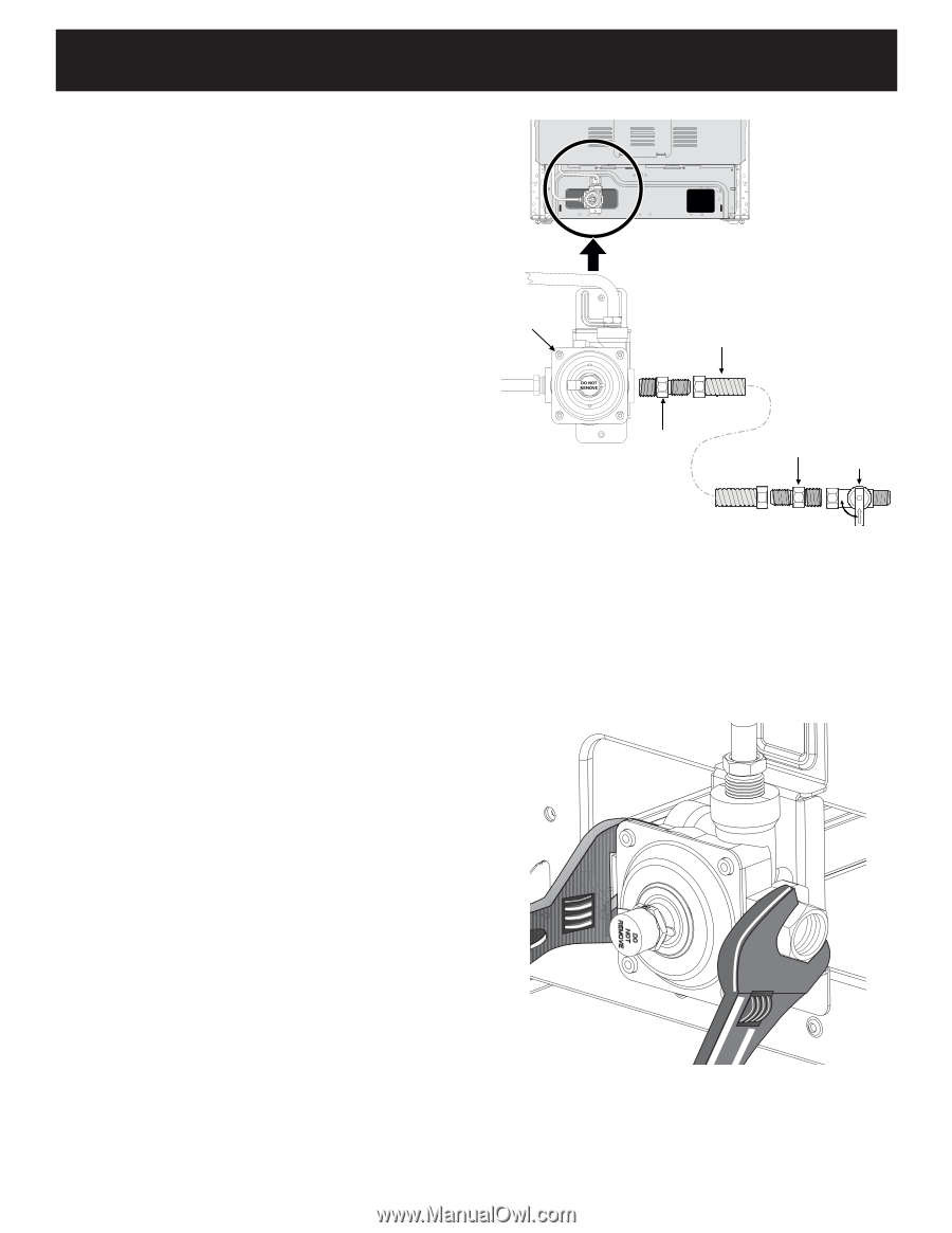
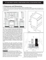
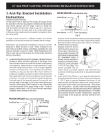
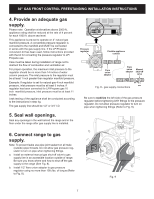
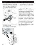
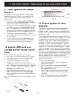
30" GAS FRONT CONTROL FREESTANDING INSTALLATION INSTRUCTIONS 4. Provide an adequate gas supply. Please note: Operation at elevations above 2000 ft., appliance rating shall be reduced at the rate of 4 percent for each 1000 ft. above sea level. This appliance is pre-set to operate on 4" natural gas manifold pressure. A convertible pressure regulator is connected to the manifold and MUST be connected in series with the gas supply line. If the LP/Propane conversion kit has been used, follow instructions provided with the kit for converting the pressure regulator to LP/ Propane use. Care must be taken during installation of range not to obstruct the flow of combustion and ventilation air. For proper operation, the maximum inlet pressure to the regulator should be no more than 14 inches of water column pressure. The inlet pressure to the regulator must be at least 1 inch greater than regulator manifold pressure. Example: If regulator is set for natural gas 4 inch manifold pressure, inlet pressure must be at least 5 inches; if regulator has been converted for LP/Propane gas 10 inch manifold pressure, inlet pressure must be at least 11 inches. Leak testing of the appliance shall be conducted according to the instructions in step 4g. The gas supply line should be 1/2" or 3/4" I.D. Pressure regulator Flexible appliance conduit Flare union adaptor Flare union adaptor Manual shut-off valve ON Fig. 8 - gas supply connections OFF Be sure to stabilize the left side of the gas pressure regulator before tightening ANY fittings to the pressure regulator. Do not allow pressure regulator to turn on pipe when tightening fittings (Refer to Fig. 9). 5. Seal wall openings. Seal any openings in the wall behind the range and in the floor under the range after gas supply line is installed. 6. Connect range to gas supply. Note: To prevent leaks use pipe joint sealant on all male (outside) pipe threads. Do not allow gas pressure regulator to turn on pipe when tightening fittings. a. Install an external manual gas shut-off valve to gas supply line in an accessible location outside of range. Be sure you know where and how to shut off the gas supply to the range (See Fig. 8). b. Install 1/2" flare union adapter to gas pressure regulator using no more than 15ft./lbs. of torque (Refer to Fig. 8). Fig. 9 7
-
 1
1 -
 2
2 -
 3
3 -
 4
4 -
 5
5 -
 6
6 -
 7
7 -
 8
8 -
 9
9 -
 10
10 -
 11
11 -
 12
12 -
13
-
14
-
15
-
16
-
17
-
18
-
19
-
20
-
21
-
22
-
23
-
24
-
25
-
26
-
27
-
28
-
29
-
30
-
31
-
32
-
33
-
34
-
35
-
36
-
37
-
38
-
39
-
40
 |
 |