Frigidaire FGHD2433KF Wiring Diagram (All Languages) - Page 2
Service Dat, A Sheet - dishwasher
 |
UPC - 012505111518
View all Frigidaire FGHD2433KF manuals
Add to My Manuals
Save this manual to your list of manuals |
Page 2 highlights
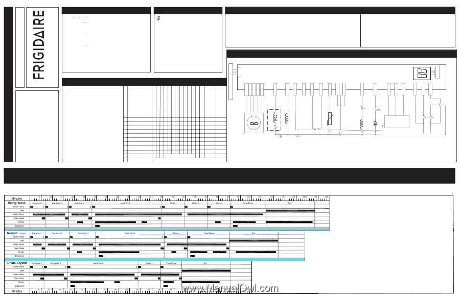
P/N: 154768201 Electronic Series P6 DISPLAY P2- 4 ELECTRONIC P2- 5 CONTROL P2- 6 BOARD P-5 W P2-1 R P2-2 BK P2-3 BK P3-5 BK P1 W P3-6 Display flashes when Detection of failure USER INTERFACE SWITCH SERVICE DATA SHEET Operation To start Close and latch door. Press START/CANCEL pad. To delay start Close and latch door. Press DELAY START pad to To select a new cycle or option select desired delay time. Press desired cycle and/or option pad. The indicator lights will change. Press START/CANCEL within 15 seconds to begin cycle. To cancel cycle Press START/CANCEL. Dishwasher will drain for For controls 90 seconds, then shut off. lock P. ress and hold the RINSE ONLY or AIR DRY pad for 3 seconds. To unlock, press and hold the RINSE ONLY or AIR DRY pad for 3 seconds. Display Codes (Readout) or LO..Low liquid in the rinse aid dispenser PF..........A power failure has occurred HO or Hd.........Water heating delay CL..........Close and latch the door ER/ER....Switch Failure ER/CE....Configuration Error ER/uo.....Vent will not close ER/uF.....Fan not running '01-24'....Hour(s) delay before start (Some models) Display Codes (LED) SENSING Turbidity sensor is checking the condition of the wash/rinse water. No sensing for LIGHT WASH (UPPER RACK), LIGHT WASH (LOWER RACK) and CHINA/CRYSTAL. WASHING Wash portion of cycle. SANITIZED The SANITIZED criteria has been met. Indicator light will switch off when door is opened. DRYING Drying portion of cycle. CLEAN Shows completion of cycle. Indicator light will switch off when door is opened. OPTION LED's Flashing -- HI-TEMP WASH and NO HEAT DRY/POWER DRY OFF LED's flashing indicates power failure has occurred. Press START/CANCEL pad and reselect desired options and cycle. STATUS LED's Flashing -- The STATUS LED's that are lit when the door is opened will flash. Close door. RINSE AGENT LOW ------- The liquid rinse agent is low. Light will switch off after 5 complete wash cycles or dispenser is (Some models) filled. Wiring Diagram Color Code BK Black BU Blue PK Pink R Red R-BK Red/Black W White Y-BK Yellow/Black DOOR L1 BK SWITCH NEUT W This information is intended for use by persons having electrical and mechanical training and a level of knowledge of these subjects generally considered acceptable in the appliance repair trade. Electrolux Home Products North America cannot be responsible, nor assume any liability, for injury or damage of any kind arising from the use of this Service Data Sheet. Water/Service Test The water/service test is a special function initiated from the power failure mode or idle mode. While in power failure or idle mode - simultaneously press the DRY/AIR DRY and START/CANCEL pads for 3 seconds. The dishwasher will then step through the test cycle per the chart. Pushing the START/CANCEL pad will advance the dishwasher to the next step. STEP 1 FILL/DISPENSER 2 FILL 3 WASH/HEAT 4 PAUSE 5 WASH/HEAT 6 WASH/HEAT/DISP. 7 DRAIN 8 DRY TOTAL TOTAL TIME (SEC) WATER VALVE CIRCULATION MOTOR DRAIN MOTOR HEATER DISPENSER FAN UNIT SENSING LED WASHING LED SANITIZED LED DRYING LED CLEAN LED RINSE LED Device being monitored 60 1 0 0 0 1 0 1 1 0 0 0 0 Fan damper Uo 27 1 0 0 0 0 0 1 1 0 0 0 0 Turbidity Tu 45 0 1 0 1 0 0 1 1 0 0 0 0 Hall sensor HS 0.4 0 0 0 1 0 0 1 1 0 0 0 1 75 0 1 0 1 0 0 0 0 0 0 0 1 60 0 1 0 1 1 0 0 0 0 0 0 1 Thermistor Th 90 0 0 1 0 0 1 0 0 0 0 0 0 Fan speed UF 90 0 0 1 X 0 1 0 0 0 1 0 0 Rinse aid RA 447 00 1 01 0 X - denotes selectable option CLEAN LED stays on until door is opened or cycle is started. FAN DRY UNIT Cycle Selection Options BK R BK-W R-W Y/BL P32-9 P32-6 P2-11 P2-12 P2-13 PUMP MOTOR W HALL SENSOR DRAIN MOTOR W RINSE AID LEVEL SENSE DISPENSER W BU P3-4 VIO P3-2 Y P3-8 P3-7 BK P2- 7 BK P2- 8 R-Y P3- 3 R W BK FLOAT SWITCH PK WATER VALVE W HEATER W P3- 1 HI-LIMIT THERMOSTAT R P1 TURBIDITY SENSOR/ THERMISTOR W 120VAC 60HZ
-
 1
1 -
 2
2
 |
 |