Frigidaire FGMC2765PB Wiring Diagram - Page 1
Frigidaire FGMC2765PB Manual
 |
View all Frigidaire FGMC2765PB manuals
Add to My Manuals
Save this manual to your list of manuals |
Page 1 highlights
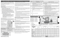
SERVICE DATA SHEET - Microwave Combination Unit with ES525/530 Electronic Oven Control NOTICE: This service data sheet is intended for use by persons having electrical and mechanical training and a level of knowledge of these subjects generally considered acceptable in the appliance repair trade. The manufacturer cannot be responsible, nor assume any liability, for injury or damage of any kind arising from the use of this data sheet. IMPORTANT NOTE: This unit includes an EOC (electronic oven control). This board is not field-repairable. Safe Servicing Practices To avoid the possibility of personal injury and/or property damage, it is important that safe servicing practices be observed. The following are some, but not all, examples of safe practices. 1. Do not attempt a product repair if you have any doubts as to your ability to complete it in a safe and satisfactory manner. 2. Before servicing or moving an appliance, remove power cord from elec- tric outlet, trip circuit breaker to Off, or remove fuse. 3. Never interfere with the proper installation of any safety device. 4. Use only replacement parts specified for this appliance. Substitutions may not comply with safety standards set for home appliances. 5. Grounding: The standard color coding for safety ground wires is green or green with yellow stripes. Ground leads are not to be used as current carrying conductors. It is extremely important that the service technician reestablish all safety grounds prior to completion of service. Failure to do so will create a potential hazard. 6. Prior to returning the product to service, ensure that: • All electric connections are correct and secure. • All electrical leads are properly dressed and secured away from sharp edges, high-temperature components, and moving parts. • All uninsulated electrical terminals, connectors, heaters, etc. are adequately spaced away from all metal parts and panels. • All safety grounds (both internal and external) are correctly and securely reassembled. • All panels are properly and securely reassembled. GROUNDING INSTRUCTIONS This oven is equipped with a three prong grounding plug. It must be plugged into the wall oven receptacle that is properly installed and grounded in accordance with the National Electrical Code and local codes and ordinances. In the event of an electrical short circuit, grounding reduces the risk of electric shock by providing an escape wire for the electric current. WARNING: Improper use of the grounding plug can result in a risk of electric shock. DOOR SENSING AND PRIMARY INTERLOCK SWITCHES The primary interlock switch is mounted in the lower position of the latch hook and the door sensing switch in the secondary interlock system is mounted in the upper position of the latch hook. They are activated by the latch heads on the door. When the door is opened, the switches interrupt the power to all high voltage components. A cook cycle cannot take place until the door is firmly closed thereby activating both interlock switches. The secondary interlock system consists of the door sensing switch and secondary interlock relay located on the control circuit board. MONITOR SWITCH The monitor switch is activated (the contacts opened) by the latch head on the door while the door is closed. The switch is intended to render the oven inoperative, by means of blowing the monitor fuse, when the contacts of the secondary interlock relay (RY2) and primary interlock switch fail to open when the door is opened. Functions: 1. When the door is opened, the monitor switch contact close (to the ON condition) due to their being normally closed. At this time the secondary interlock relay (RY2) and primary interlock switch are in the OFF condition (contacts open) due to their being normally open contact switches. 2. As the door goes to a closed position, the monitor switch contacts are first opened and then the door sensing switch and the primary interlock switch contacts close. (On opening the door, each of these switches operate inversely.) 3. If the door is opened, and the secondary interlock relay (RY2) and primary interlock switch contacts fail to open, the monitor fuse blows simultaneously with closing of the monitor switch contacts. CAUTION: BEFORE REPLACING A BLOWN MONITOR FUSE TEST THE DOOR SENSING SWITCH, SECONDARY INTERLOCK RELAY (RY2), RELAY (RY1), PRIMARY INTERLOCK SWITCH AND MONITOR SWITCH FOR PROPER OPERATION. (REFER TO CHAPTER «TEST PROCEDURE»). NOTE: MONITOR FUSE AND MONITOR SWITCH ARE REPLACED AS AN ASSEMBLY. CAVITY TEMPERATURE FUSE The cavity temperature fuse located on the top of the oven cavity, is designed to prevent damage to the oven by fire. If the food load is overcooked, by either error in cook time or defect in the control unit, the cavity temperature fuse will open. Electrical Requirements The electrical requirements are a 120 volt 60 Hz, AC only, a branch circuit protection fuse, 20 amp is provided in series with the ac outlet on top of the wall oven support. *Note: Branch circuit fuse 20 amp shall be replaced with class cc type. Data Sheet Abbreviations and Terminology Under normal operation, the cavity temperature fuse remains closed. However, when ab- normally will open haitg3h0t2eOmFp(e1r5a0tuOreCs) are reached causing the within the oven cavity, oven to shut down. the cavity temperature fuse NOTE: This is fuse. It does not reset. MONITOR FUSE 1. The monitor fuse blows when the contacts (COM-NO) of the primary interlock relay (RY2) and secondary interlock switch remain closed with the oven door open and when the monitor switch closes. 2. If the wire harness or electrical components are short-circuited, this monitor fuse blows to prevent an electric shock or fire hazard. DLB - Double Line Break EOC - Electronic Oven Control LED - Light-Emitting Diode MDL - Motor Door Latch PS - Power supply board (PS1, PS2, RTD - Resistance Temperature etc) Detector/Oven Probe MAGNETRON TEMPERATURE FUSE The magnetron temperature fuse located near the magnetron is designed to prevent damage to the magnetron if an over heated condition develops in the tube due to cooling fan failure, obstructed air guide, dirty or blocked air intake, etc. TCO - Thermal cut out, also "thermo VSC - Variable Speed Control disc" or "thermal limiter" IMPORTANT DO NOT REMOVE THIS BAG OR DESTROY THE CONTENTS WIRING DIAGRAMS AND SERVICE INFORMATION ENCLOSED REPLACE CONTENTS IN BAG Under normal operation, the magnetron temperature fuse remains closed. However, when abnormally high temperatures are reached within the magnetron, the magnetron temperature fuse will open at 302°F(150°C) causing the oven to shut down. NOTE: This is a fuse. It does not reset. 807574801 EN Rev A (13/05) Electronic Oven Control (EOC) Fault Code Descriptions Code Condition / Cause Suggested Corrective Action F10 Control has sensed a potential runaway oven condition, Check RTD sensor probe and replace, if necessary. If oven is overheating, disconnect control may have shorted relay, and/or RTD sensor probe power. If oven continues to overheat when power is reapplied, replace the Electronic may have gone bad. Oven Control (EOC). F11 Shorted Key: A key has been detected as pressed (for a 1. Press STOP key. long period). Will be considered a shorted key alarm and 2. If the problem persists, replace the EOC. will terminate all oven activity. F13 Control's internal checksum may be corrupted. • Press CLEAR key. - Disconnect power, wait 10 seconds, and reapply power. If fault returns upon power-up, replace EOC. F14 Misconnected flat cables. No communication between oven 1. Disconnect power. Verify the flat cable connection between the touch panel or and controls. membrane and the EOC on P12 and P13. 2. If the problem persist, replace the EOC. F30 Open RTD sensor probe/ wiring problem. Note: EOC may 1. Check wiring in probe circuit for possible open or short condition. or initially display an "F10," thinking a runaway condition 2. Check RTD resistance at room temperature (compare to probe resistance chart). If exists. resistance does not match the chart, replace the RTD sensor probe. F31 Shorted RTD sensor probe /wiring problem. 3. Let the oven cool down and restart the function. 4. If the problem persists, replace the EOC. F90 to Door motor mechanism failure. F94 1. Turn off power for 10 seconds, then turn on power. Test the door latch again (try to start a Clean cycle). 2. If it fails, check wiring of Lock Motor, Lock Switch and Door Switch circuits. 3. Unplug the lock motor from the board and apply power (L1) directly to the Lock Motor. If the motor does not rotate, replace Lock Motor Assembly. 4. Check Lock Switch for proper operation (do the contacts open and close, check with ohmmeter). The Lock Motor may be powered as in above step to open and close Lock Switch. If the Lock Switch is defective, replace Motor Lock Assembly. 5. If all above steps fail to correct situation, replace the EOC. Note: Generally speaking, F1X implies a control failure, F3X an oven probe problem, and F9x a latch motor problem. RTD SCALE Temperature °F (°C) Resistance (ohms) 32 ± 1.9 (0 ± 1.0) 1000 ± 4.0 75 ± 2.5 (24 ± 1.3) 1091 ± 5.3 250 ± 4.4 (121 ± 2.4) 1453 ± 8.9 350 ± 5.4 (177 ± 3.0) 1654 ± 10.8 450 ± 6.9 (232 ± 3.8) 1852 ± 13.5 550 ± 8.2 (288 ± 4.5) 2047 ± 15.8 650 ± 9.6 (343 ± 5.3) 2237 ± 18.5 900 ± 13.6 (482 ±7.5) 2697 ± 24.4 Probe circuit to case ground Open circuit/infinite resistance P1. L2 Out P3. L2 In P5. L1 Input P7. Broil Connector P9. Bake Connector P11. Convection Element Connector P15. L1 Input J3 P2 P15 J4 P6 K9 K11 K14 K16 K18 J3 P11 K1 K7 K5 K3 P5 P3 P17 P1 P11 P9 P7 J3. Relay Outputs : Convection Fan, Motor Door Latch, Oven Light, Cooling Fan. Power Input (L1 and Neutral). P11. Door switch, Motor Door Latch Switch and Oven Probe Inputs. OVEN CIRCUIT ANALYSIS MATRIX ELEMENTS On Relay Board Oven Light Conv. Fan Door Motor Cooling Fan Low Cooling Fan High Bake P9 Broil P7 Conv. P11 J3-3 J3-5 J3-4 Speed J3-2 Speed J3-1 DLB L2 Out P1 Preheat X X X X X X X Bake X X X* X* X X X Broil X X X X Convection Bake X X X X X X X Convection Roast X X X X X X X Convection Broil X X X X X Clean X X X X X Locking / Unlocking X Light X Door Open X Door Closed * Convection element and fan are used for the first rise of temperature. Relay will operate in this condition only On Display Board Door Switch P11-4 / P11-3 X
-
 1
1 -
 2
2 -
 3
3 -
 4
4
 |
 |
