Frigidaire FGMC3066UF Wiring Diagram - Page 2
Modular Control Systems - lowes
 |
View all Frigidaire FGMC3066UF manuals
Add to My Manuals
Save this manual to your list of manuals |
Page 2 highlights
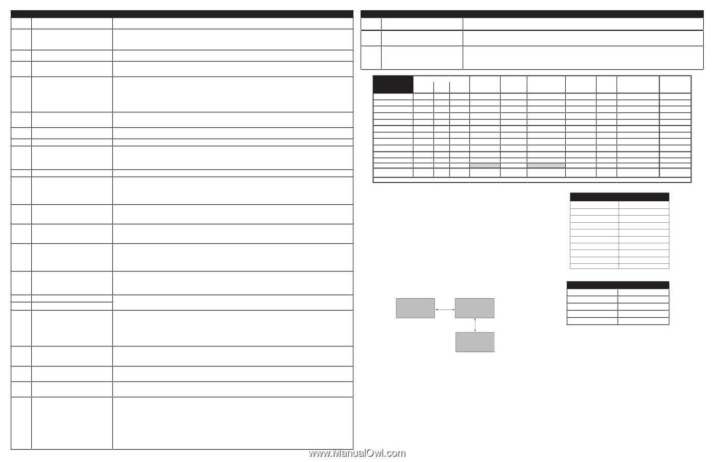
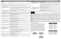
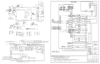
Fault Code F01 F02 F04 F05 Description of Error Code Touch panel failure ELECTRONIC OVEN CONTROL (EOC) FAULT CODE DESCRIPTIONS Suggested Corrective Action Disconnect power, wait 30 seconds and reapply power. If fault returns upon power-up replace the touch panel. F03 The oven user interface board is incorrectly Replace the oven user interface board. Make sure you install the latest revision available for this model. configured. F10 Oven temperature runaway: the cavity tem- 1. If oven is overheating, disconnect power. Check oven temperature probe (RTD) and replace if necessary. perature has been detected in excess of the 2. If the oven temperature probe is good and if oven continues to overheat when power is reapplied, replace the oven relay board. maximum safe operating temperature. F11 Stuck key: a key has been detected has pressed 1. If a key was pressed inadvertently for a long time this error code will be displayed. Make sure there is nothing (water, utensils) in contact with continuously for 30 seconds or more. the keyboard. The fault code should go away once the key is released and the Stop key is pressed. If the F011 error comes back when a key is pressed it means the error condition is still there. If the F011 error does not come back it means the error condition is gone and the oven can be used. 2. If the fault code cannot be cleared, test the wiring harness between oven user interface board (connector I2C1 or I2C2) and touch panel (connec- tor I2C1 or I2C2). 3. If the fault code cannot be cleared and the wiring is good, the touch panel is most likely defective: replace the touch panel. 4. If changing the touch panel did not fix the problem replace the oven user interface board. F12 Keyboard configuration alarm: the oven user 1. Verify the unit has the proper oven user interface board and touch panel, based on the model number and parts catalog. interface board received from the touch panel a 2. Replace the oven user interface board. key code that does not match the key map. 3. If the problem persists replace the touch panel. F13 Data written to non-volatile memory has failed Disconnect power, wait 30 seconds and reapply power. If fault returns upon power-up replace the oven user interface. verification F15 Keyboard error Disconnect power, wait 30 seconds and reapply power. If fault returns upon power-up replace the touch panel. F17 The oven user interface board is unable to configure the touch panel. 1. Disconnect power to the unit, wait 30 seconds, then reapply power. 2. If fault returns, verify harness going to I2C1 or I2C2 connector of the touch panel. 3. Verify the unit has the proper oven user interface board and touch panel, based on the model number and parts catalog. 4. If fault persists, replace the oven user interface. 5. If fault persists, replace the touch panel. F18 Oven relay board failure (wiggler) Replace the oven relay board. F19 The oven user interface board is unable to configure the oven relay board 1. Disconnect power to the unit, wait 30 seconds, then reapply power. 2. If fault returns, verify connection between the oven user interface board (MACS1 or MACS2 connector) and the oven relay board (connector J3 or J4). 3. Verify the unit has the proper oven user interface board and oven relay board, based on the model number and parts catalog. 4. If fault persists, replace oven user interface board. 5. If fault persists, replace the relay board. F22 Communication failure between the oven user 1. Disconnect power, wait 30 seconds and reapply power. Check if error condition is still there. interface board and the oven relay board 2. Test wiring harness between oven user interface board (connector MACS1 or MACS2) and oven relay board (connector J3 or J4). 3. If wiring harness is good replace oven relay board. 4. If the problem persists replace the oven user interface. F23 Communication failure between the oven user 1. Disconnect power, wait 30 seconds and reapply power. Check if error condition is still there. interface board and the glass touch panel 2. Test wiring harness between oven user interface board (connector I2C1 or I2C2) and touch panel (connector I2C1 or I2C2). 3. If wiring harness is good replace touch panel. 4. If the problem persists replace the oven user interface. F25 The communication between the over user 1. Disconnect power to the unit, wait 30 seconds, then reapply power. F27 interface and the oven relay board cannot be 2. If fault returns, verify connection between the oven user interface board (MACS1 or MACS2 connector) and the oven relay board (connector J3 initiated. or J4). 3. Verify the unit has the proper oven user interface board and oven relay board, based on the model number and parts catalog. 4. If fault persists, replace relay board. 5. If fault persists, replace the oven user interface board. F28 The communication between the over user inter- 1. Disconnect power to the unit, wait 30 seconds, then reapply power. F29 face and the touch panel cannot be initiated. 2. If fault returns, verify touch panel is connected (verify harness going to I2C1 or I2C2 connector) and is getting power from the oven user interface. 3. Verify the unit has the proper oven user interface board and touch panel, based on the model number and parts catalog. 4. If fault persists, replace the touch panel. 5. If fault persists, replace the oven user interface. F30 Open oven temperature sensor (RTD) F31 Shorted oven temperature probe (RTD) 1. Check probe circuit wiring for possible open or short condition. 2. Verify RTD resistance at room temperature (compare to probe resistance chart). If resistance does not match the chart, replace the RTD probe. 3. If the problem persists replace the oven relay board. F33 Meat probe temperature sensor shorted or too 1. The error is triggered if the meat probe sees a temperature in excess of 392°F. Make sure the meat probe was not used in such way that it could hot have seen such temperature. If the tip of the probe is not inserted in the meat it will see the cavity temperature, which can be higher than 392°F (depending on the setpoint) and trigger the alarm. 2. When the meat probe is connected to the socket inside the oven cavity, if the meat probe is not fully inserted into the socket it may short the contacts and cause the error. Make sure the probe is inserted as much as it can. 3. Verify meat probe resistance at room temperature. Compare to meat probe resistance chart. If the meat probe does not match the chart, replace it. 4. If the above steps failed to correct the problem, replace the oven relay board. F45 Cooling fan speed too low. 1. Check if the cooling fan blades are blocked. 2. Confirm tachometer harness is connected on fan and on oven control. 3. Replace cooling fan. 4. Replace oven control. F46 Cooling fan speed too high. 1. Check for mechanical obstruction in the air path. 2. Replace cooling fan. 3. Replace oven control. F50 A/D Out of Range: the oven relay board is unable 1. Check to ensure that the connections between the door switch, MDL and temp probes are properly connected. This includes all splices and to read the status of the switches (door, MDL) junctions. 2. If the above step failed to correct the problem, replace the oven relay board. F90 Motor Door Lock mechanism failure. The oven 1. Disconnect power to the unit, wait 30 seconds, then reapply power. Try again to make the door lock or unlock (ex: initiate a Lockout or a Clean control does not see the Motor Door Lock cycle). running. 2. Check if the Lock Motor is running or not. If it is not running, test the wiring between the Lock Motor and the oven relay board. If the wiring is good, check if there is 120VAC at the motor when it is expected to run to see if the failure originates from a bad motor (120VAC present but not turning) or a problem with the relay board (J20 pin 10 on the oven relay board is the output to the Lock Motor). The Lock Motor can also be test- ed by applying 120VAC directly to the motor (unplug it from the relay board first). If the Lock Motor does not run when 120VAC is applied replace the Lock Motor Assembly. If it is the relay board that does not provide 120VAC to the Lock Motor replace the oven relay board. 3. If the Lock Motor is running but the oven control cannot find the locked or unlocked position (ex: motor turns continuously until F90 fault code is generated) the Lock Switch needs to be verified. Check wiring between Lock Switch and oven relay board. Verify with ohmmeter if the switch makes contact properly (verify continuity with ohmmeter when the switch is pressed). If the Lock Switch is defective replace the Motor Lock Assembly. 4. If all above steps failed to correct the situation, replace the oven relay board. Fault Code F95 F96 Description of Error Code ELECTRONIC OVEN CONTROL (EOC) FAULT CODE DESCRIPTIONS Suggested Corrective Action Motor Door Lock mechanism failure. The Motor 1. Door Lock does not stop running or the Lock Switch sends an invalid signal. 2. The oven door has been detected open during a 1. Self Clean cycle. 2. 3. The problem can be caused by a faulty Lock Switch or by a defective oven relay board. If the Motor Door Lock is always running (as if the relay controlling it is stuck closed) replace the oven relay board. If the motor is not always running replace the Motor Lock Assembly. This error occurs if the door switch has lost its contact during a Self Clean cycle. Make sure the oven door closes well and fully presses on the door switch plunger when the door is locked, and no one attempted to pull on the oven door during the Self Clean cycle. Test continuity of wiring between the door switch and the oven relay board, make sure the door switch is well connected. With an ohmmeter, verify the switch is closed when the plunger is pressed. If the door switch is found to be defective replace the door switch. If the switch and wiring are good and the problem persists, replace the oven relay board. CIRCUIT ANALYSIS MATRIX Bake Bake P7 (K3) X Elements Broil K2 X Conv. P8 (K6) X Door Motor J20-10 (K13) Light J20-6 (K9) Conv. Fan Low J20-9 (K12) High J19-3 (K6) X Door Switch J5-7, J5-9 DLB L2 out (K1) X Cooling Fan Low J20-7 (K10) High J20-8 (K11) X Catalyst "Air Guard" J19-2 (K5) X Broil X X X Conv. Bake X X X X X X X Conv. Roast X X X X X X X Clean X X X X X X Locking X Locked Unlocking X Unlocked Light X Door Open X X Door Closed Air Guard X X X (with key press) X NOTES: Bake, broil, and convection elements alternate cycles. Convection fans may run during preheat and may run intermittently during non-convection functions to improve cooking performance. Modular Control Systems This appliance is equipped with a modular system of controls. The modular system consists of various boards which communicate with one another to drive cooking functions. Oven functions, if available, operate through an oven user interface (UI or UIB) and an oven relay board. Cooktop functions, if available, operate through a cooktop UI/UIB and a cooktop relay board. There may be additional boards which work within the system to drive specific functions (refer to the schematics and diagrams and this sheet). Low voltage operating and communications power for the modular boards is provided through the wiring schemes. The boards that generate low voltage operating and communications power depend upon the individual control system (refer to the schematics and diagrams on this sheet). These voltages are only the operational voltages. Do not use these voltages as confirmation of communication between the boards. Communication occurs through software programming on each board. This communication is not detectable by volt ohmmeters. The programming is self-monitored and the UI displays will show error codes based on detected failures. The individual boards are not field repairable. See the schematics and diagrams included on this sheet for more unit-specific details. OVEN CONTROL RELAY BOARD (OVC) MACS OVEN CONTROL (MARS) I2C RTD SCALE Temperature °F (°C) 32 ± 1.9 (0 ± 1.0) 75 ± 2.5 (24 ± 1.3) 250 ± 4.4 (121 ± 2.4) 350 ± 5.4 (177 ± 3.0) 450 ± 6.9 (232 ± 3.8) 550 ± 8.2 (288 ± 4.5) 650 ± 9.6 (343 ± 5.3) 900 ± 13.6 (482 ±7.5) Probe circuit to case ground Resistance (ohms) 1000 ± 4.0 1091 ± 5.3 1453 ± 8.9 1654 ± 10.8 1852 ± 13.5 2047 ± 15.8 2237 ± 18.5 2697 ± 24.4 Open circuit/infinite resistance MEAT PROBE TEMPERATURE VS RESISTANCE Temperature °F (°C) Resistance (Kohm) 77 (25) 50.0 ± 7% 122 (50) 18.0 ± 4.9% 176 (80) 6.3 ± 3.3% 212 (100) 3.4 ± 4.6% TOUCH PANEL (BENDER HMI)
-
 1
1 -
 2
2 -
 3
3 -
 4
4
 |
 |