Frigidaire FPEC3677RF Installation Instructions (All Languages) - Page 7
Checking Operation, Model and Serial Number Location, Before You Call for Service
 |
View all Frigidaire FPEC3677RF manuals
Add to My Manuals
Save this manual to your list of manuals |
Page 7 highlights
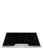
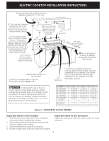
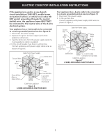
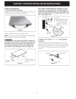
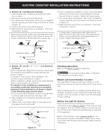
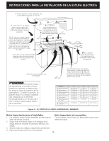
ELECTRIC COOKTOP INSTALLATION INSTRUCTIONS 3. Models: 32" Coil Elements Cooktops 1. Place cooktop into countertop opening and center unit in cutout. 2. Remove all surface units and drip bowls. 3. Unit clamp down information. Once unit is installed in counter opening, you must clamp unit down as shown in figure 12. 4. Put back all surface units and drip bowls. 5. Make electrical connections as outlined in "Electrical Connection" section. Reach down through surface unit openings and install the four hold down retainers with screws as shown. Be certain cooking top is firmly retained to counter top. Cooktop Nylon spacer 4. Prior to tightening installation screws, exert downward pressure on burner box to assure flanges on burner box rest firmly on counter. Tighten all screws evenly. 5. Unit clamp down information. Once unit is installed in counter opening, you must clamp unit down as shown in figure 14. 6. Make electrical connections as outlined in "Electrical Connection" Section. To clamp down, insert bracket with offset side of angle into slot on each side of unit. The screw should then be run through bracket and against bottom of counter. Tighten until draws down. Cooktop Countertop Hold down retainer Countertop Burner box Figure 12 4. Models: 30" and 36" (36" X 21½") Coil Elements Cooktops - These cooktops are designed to fit various cutout sizes. The minimum and maximum cutout openings are shown in figure 1. - If cooktop is to be used in new installation, use minimum cutout dimensions in figure 1. - Attach cooktop to cabinet using wood screws through holes in vertical walls of burner box. - If cooktop is to be installed as a replacement in an existing countertop opening (not exceeding maximum cutout dimensions as shown in figure 1), the following steps must be taken: 1. Insert 4 screws and installation spacers through holes in vertical walls of burner box (see figure 13). 2. Place cooktop into countertop opening and center unit in cutout. 3. Tighten each screw finger tight or until spacers are snug against burner box walls. Spacer Burner box Screw Hold down retainer Screw Burner box Figure 14 Checking Operation Refer to the Owner's Guide for operation. CAUTION Do not touch cooktop glass or elements. They may be hot enough to burn. Model and Serial Number Location The serial plate is located under the cooktop or in the burner box and can be seen by lifting up the main top of unit. When ordering parts for or making inquires about your cooktop, always be sure to include the model and serial numbers and a lot number or letter from the serial plate on your cooktop. Before You Call for Service Read the Avoid Service Checklist and operating instructions in your Owner's Guide. It may save you time and expense. The list includes common occurrences that are not the result of defective workmanship or materials in this appliance. Refer to the warranty in your Owner's Guide for our service phone number and address. Please call or write if you have inquiries about your product and/or need to order parts. Figure 13 7
-
 1
1 -
 2
2 -
 3
3 -
 4
4 -
 5
5 -
 6
6 -
 7
7 -
 8
8 -
 9
9 -
 10
10 -
 11
11 -
 12
12 -
13
-
14
-
15
-
16
-
17
-
18
-
19
-
20
-
21
-
22
-
23
-
24
 |
 |
