Frigidaire FPGH3077RF Wiring Diagram - Page 1
Frigidaire FPGH3077RF Manual
 |
View all Frigidaire FPGH3077RF manuals
Add to My Manuals
Save this manual to your list of manuals |
Page 1 highlights
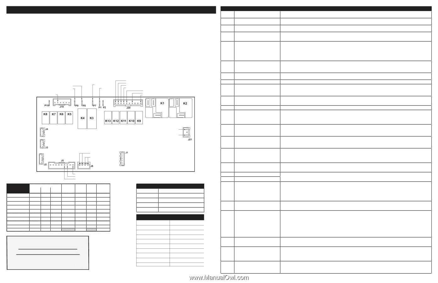
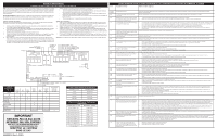
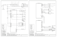
SERVICE DATA SHEET GAS RANGES WITH MODULAR OVEN CONTROLS NOTICE: This service data sheet is intended for use by persons having electrical and mechanical training and a level of knowledge of these subjects generally considered acceptable in the appliance repair trade. The manufacturer cannot be responsible, nor assume any liability, for injury or damage of any kind arising from the use of this data sheet. IMPORTANT NOTE: This unit includes an EOC (electronic oven control). This board is not field-repairable.Verify the unit has the proper oven relay board, oven user interface board, and touch panel based on the model number and parts catalog. 6. Prior to returning the product to service, ensure that: • All electric connections are correct and secure. • All electrical leads are properly dressed and secured away from sharp edges, high-temperature components, and moving parts. • All uninsulated electrical terminals, connectors, heaters, etc. are adequately spaced away from all metal parts and panels. • All safety grounds (both internal and external) are correctly and securely reassembled. • All panels are properly and securely reassembled. Safe Servicing Practices To avoid the possibility of personal injury and/or property damage, it is important that safe servicing practices be observed. The following are some, but not all, examples of safe practices. 1. Do not attempt a product repair if you have any doubts as to your ability to complete it in a safe and satisfactory manner. 2. Before servicing or moving an appliance, remove power cord from electric outlet, trip circuit breaker to Off, or remove fuse. 3. Never interfere with the proper installation of any safety device. 4. Use only replacement parts specified for this appliance. Substitutions may not comply with safety standards set for home appliances. 5. Grounding: The standard color coding for safety ground wires is green or green with yellow stripes. Ground leads are not to be used as current carrying conductors. It is extremely important that the service technician reestablish all safety grounds prior to completion of service. Failure to do so will create a potential hazard. Temperature Adjustment 1. Make sure both the oven mode selector and the oven temperature selector are in the OFF position. Press and hold both the light icon and the clock icon at the same time for a few seconds until the display sounds an acceptance chime. AUd should appear in the display. 2. Press the + key in the upper part of the display until UPO appears and the default setting of 0° (or the last set temperature offset) is showing. 3. Using the + or - key in the bottom of the display, press until the desired temperature change (offset) is reached. The display will change ± 5° with each key press to a maximum of +35° or a minimum of -35°F. Once the new offset appears in the display, release the key and the control will accept the change. 4. To return the display to normal, press and hold both the oven light icon and the clock icon at the same time until an acceptance chime sounds. The display will return to show the time of day. Note: Changing calibration affects all baking modes. The adjustments made will not change the broil self-cleaning temperature. BAKE IGNITER L1 IN CONVECTION ELEMENT BROIL IGNITER L1 IN MOTOR DOOR LATCH (MDL) CONVECTION FAN COOLING FAN-LO COOLING FAN-HI OVEN LAMP L1 IN NEUTRAL 1 1 1 CONNECTS TO USER INTERFACE BOARD 1 1 L1 NEUTRAL CIRCUIT ANALYSIS MATRIX Bake Broil Conv. Bake Conv. Roast Clean Locking Unlocking Light Door Open Door Closed MEAT PROBE 1 TEMPERATURE PROBE Bake P8 X X X X 1 1 MOTOR DOOR LATCH SWITCH DOOR SWITCH COMMON Conv. Door Broil Conv. Door Motor Light Fan Switch P7 J19-2 J20-10 J20-6 J20-9 J5-7, J5-8 X X X X X X X X X X X X IMPORTANT DO NOT REMOVE THIS BAG OR DESTROY THE CONTENTS WIRING DIAGRAMS AND SERVICE INFORMATION ENCLOSED REPLACE CONTENTS IN BAG p/n A00950613 Rev A (1503) PROGRAMMING HEADER 1 MEAT PROBE TEMPERATURE VS RESISTANCE TABLE Temperature Probe Resistance 77 °F / 25°C 50.020 Kohm +/- 6% 122 °F / 50°C 18.020 Kohm +/- 5% 176 °F / 80°C 6.290 Kohm +/- 5% 212 °F / 100°C 3.400 Kohm +/- 5% RTD SCALE Temperature °F (°C) Resistance (ohms) 32 ± 1.9 (0 ± 1.0) 1000 ± 4.0 75 ± 2.5 (24 ± 1.3) 1091 ± 5.3 250 ± 4.4 (121 ± 2.4) 1453 ± 8.9 350 ± 5.4 (177 ± 3.0) 1654 ± 10.8 450 ± 6.9 (232 ± 3.8) 1852 ± 13.5 550 ± 8.2 (288 ± 4.5) 2047 ± 15.8 650 ± 9.6 (343 ± 5.3) 2237 ± 18.5 900 ± 13.6 (482 ±7.5) 2697 ± 24.4 Probe circuit to case ground Open circuit/infinite resistance Fault Code F01 F02 F04 F05 F03 F10 F11 F12 F13 F15 F16 F17 F18 F19 F22 F23 F25 F27 F28 F29 F30 F31 F33 F50 F90 F95 F96 F97 Description of Error Code ELECTRONIC OVEN CONTROL (EOC) FAULT CODE DESCRIPTIONS Suggested Corrective Action Touch panel failure Disconnect power, wait 30 seconds and reapply power. If fault returns upon power-up replace the control assembly (UIB and touch panel). The oven user interface board is incorrectly configured. Replace the control assembly (UIB and touch panel). Make sure you install the latest revision available for this model. Oven temperature runaway: the cavity tem- 1. perature has been detected in excess of the 2. maximum safe operating temperature. If oven is overheating, disconnect power. Check oven temperature probe (RTD) and replace if necessary. If the oven temperature probe is good and if oven continues to overheat when power is reapplied, replace the oven relay board. Stuck key: a key has been detected has pressed continuously for 30 seconds or more. 1. If a key was pressed inadvertently for a long time this error code will be displayed. Make sure there is nothing (water, utensils) in contact with the keyboard. The fault code should go away once the key is released and the Stop key is pressed. If the F011 error comes back when a key is pressed it means the error condition is still there. If the F011 error does not come back it means the error condition is gone and the oven can be used. 2. If the fault code cannot be cleared, test the wiring harness between oven user interface board (connector I2C1 or I2C2) and touch panel (connector I2C1 or I2C2). 3. If the fault code cannot be cleared and the wiring is good, the touch panel is most likely defective: replace the control assembly (UIB and touch panel). Keyboard configuration alarm: the oven user interface board received from the touch panel a key code that does not match the key map. Disconnect power, wait 30 seconds and reapply power. If fault returns upon power-up replace the control assembly (UIB and touch panel). Data written to non-volatile memory has failed verification Disconnect power, wait 30 seconds and reapply power. If fault returns upon power-up replace the control assembly (UIB and touch panel). Keyboard error Disconnect power, wait 30 seconds and reapply power. If fault returns upon power-up replace the control assembly (UIB and touch panel). The oven user interface board cannot read the potentiometers. 1. Verify that potentiometers are in OFF position correctly, disconnect power to the unit, wait 30 seconds, then reapply power. 2. If fault returns, verify harness going to the POTS connector of the user interface board to both potentiometer components. 3. If fault persists, replace potentiometers. 4. If fault persists, replace the control assembly (UIB and touch panel) The oven user interface board is unable to configure the touch panel. 1. Disconnect power to the unit, wait 30 seconds, then reapply power. 2. If fault returns, verify harness going to I2C1 or I2C2 connector of the touch panel. 3. If fault persists, replace the control assembly (UIB and touch panel) Oven relay board failure (wiggler) Replace the oven relay board. The oven user interface board is unable to configure the oven relay board 1. Disconnect power to the unit, wait 30 seconds, then reapply power. 2. If fault returns, verify connection between the oven user interface board (MACS1 or MACS2 connector) and the oven relay board (connector J3 or J4). 3. If fault persists, replace the control assembly (UIB and touch panel) 4. If fault persists, replace the relay board. Communication failure between the oven user interface board and the oven relay board 1. Disconnect power, wait 30 seconds and reapply power. Check if error condition is still there. 2. Test wiring harness between oven user interface board (connector MACS1 or MACS2) and oven relay board (connector J3 or J4). 3. If wiring harness is good replace oven relay board. 4. If the problem persists replace the control assembly (UIB and touch panel). Communication failure between the oven user interface board and the glass touch panel 1. Disconnect power, wait 30 seconds and reapply power. Check if error condition is still there. 2. Test wiring harness between oven user interface board (connector I2C1 or I2C2) and touch panel (connector I2C1 or I2C2). 3. If wiring harness is good replace touch panel. 4. If the problem persists replace the control assembly (UIB and touch panel). The communication between the over user interface and the oven relay board cannot be initiated. 1. Disconnect power to the unit, wait 30 seconds, then reapply power. 2. If fault returns, verify connection between the oven user interface board (MACS1 or MACS2 connector) and the oven relay board (connector J3 or J4). 3. If fault persists, replace relay board. 4. If fault persists, replace the control assembly (UIB and touch panel). The communication between the over user interface and the touch panel cannot be initiated. 1. Disconnect power to the unit, wait 30 seconds, then reapply power. 2. If fault returns, verify touch panel is connected (verify harness going to I2C1 or I2C2 connector) and is getting power from the oven user interface. 3. If fault persists, replace the control assembly (UIB and touch panel). Open oven temperature sensor (RTD) Shorted oven temperature probe (RTD) 1. Check probe circuit wiring for possible open or short condition. 2. Verify RTD resistance at room temperature (compare to probe resistance chart). If resistance does not match the chart, replace the RTD probe. 3. If the problem persists replace the oven relay board. Meat probe temperature sensor shorted or too hot 1. The error is triggered if the meat probe sees a temperature in excess of 392°F. Make sure the meat probe was not used in such way that it could have seen such temperature. If the tip of the probe is not inserted in the meat it will see the cavity temperature, which can be higher than 392°F (depending on the setpoint) and trigger the alarm. 2. When the meat probe is connected to the socket inside the oven cavity, if the meat probe is not fully inserted into the socket it may short the contacts and cause the error. Make sure the probe is inserted as much as it can. 3. Verify meat probe resistance at room temperature. Compare to meat probe resistance chart. If the meat probe does not match the chart, replace it. 4. If the above steps failed to correct the problem, replace the oven relay board. A/D Out of Range: the oven relay board is unable to read the status of the switches (door, MDL) Replace the oven relay board. Motor Door Lock mechanism failure. The oven control does not see the Motor Door Lock running. 1. Disconnect power to the unit, wait 30 seconds, then reapply power. Try again to make the door lock or unlock (ex: initiate a Lockout or a Clean cycle). 2. Check if the Lock Motor is running or not. If it is not running, test the wiring between the Lock Motor and the oven relay board. If the wiring is good, check if there is 120VAC at the motor when it is expected to run to see if the failure originates from a bad motor (120VAC present but not turning) or a problem with the relay board (J20 pin 10 on the oven relay board is the output to the Lock Motor). The Lock Motor can also be tested by applying 120VAC directly to the motor (unplug it from the relay board first). If the Lock Motor does not run when 120VAC is applied replace the Lock Motor Assembly. If it is the relay board that does not provide 120VAC to the Lock Motor replace the oven relay board. 3. If the Lock Motor is running but the oven control cannot find the locked or unlocked position (ex: motor turns continuously until F90 fault code is generated) the Lock Switch needs to be verified. Check wiring between Lock Switch and oven relay board. Verify with ohmmeter if the switch makes contact properly (verify continuity with ohmmeter when the switch is pressed). If the Lock Switch is defective replace the Motor Lock Assembly. 4. If all above steps failed to correct the situation, replace the oven relay board. Motor Door Lock mechanism failure. The Mo- 1. tor Door Lock does not stop running or the Lock Switch sends an invalid signal. 2. The problem can be caused by a faulty Lock Switch or by a defective oven relay board. If the Motor Door Lock is always running (as if the relay controlling it is stuck closed) replace the oven relay board. If the motor is not always running replace the Motor Lock Assembly. The oven door has been detected open during a Self Clean cycle. 1. This error occurs if the door switch has lost its contact during a Self Clean cycle. Make sure the oven door closes well and fully presses on the door switch plunger when the door is locked, and no one attempted to pull on the oven door during the Self Clean cycle. 2. Test continuity of wiring between the door switch and the oven relay board, make sure the door switch is well connected. With an ohmmeter, verify the switch is closed when the plunger is pressed. If the door switch is found to be defective replace the door switch. 3. If the switch and wiring are good and the problem persists, replace the oven relay board. MDL invalid state. Relay board (OVC) sensed the motor door lock in a state it should not be in according to the user interface board. 1. Disconnect power to the unit, wait 30 seconds, then reapply power. 2. If fault persists, replace motor door lock. 3. If fault persists, replace the oven relay board.
-
 1
1 -
 2
2 -
 3
3 -
 4
4
 |
 |