Frigidaire FRU17G4JW Wiring Diagram (All Languages) - Page 1
Frigidaire FRU17G4JW - Broan : 16.7 cu. Ft. All Refrigerator Manual
 |
UPC - 012505218590
View all Frigidaire FRU17G4JW manuals
Add to My Manuals
Save this manual to your list of manuals |
Page 1 highlights
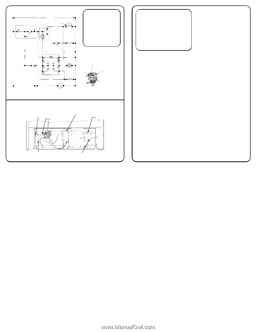
ELECTRICAL CIRCUIT Power Blk Cold Control See Diagram Defrost On/Off Thermostat Timer Yel Wh Compressor Blu Red Or Defrost Thermostat Defrost Heater IMPORTANT If any green grounding wires are removed during servicing, they must be returned to their original position and properly secured. WIRING DIAGRAM EC82 Ambient Thermostat Blk Door Switch Wh Yel Yel Fan Relay Pur Brn Evaporator Fan Pur Auxiliary Heater Interior Light C S White Blanc Blanco Yellow Jaune Armarillo Overload Surcharge Protector termico R de sobrecarga Relay Relais Rele C09 SYSTEM SCHEMATIC Condenser Outlet Heat Exchanger Charge Tube Charge Tube Drier SP24 Discharge IMPORTANT SAFETY NOTICE The information provided herein is designed to assist qualified repair personnel only. Untrained persons should not attempt to make repairs due to the possibility of electrical shock. Disconnect power cord before servicing. 216946200 SERVICE DATA SHEET AUTOMATIC DEFROST SINGLE DOOR REFRIGERATOR INSTALLATION This product is designed for "free standing installation only" and three inches of clearance must be provided on all sides of the refrigerator for air circulation. The refrigerator should be positioned on a solid floor, and the front of the cabinet should be raised just enough to provide easy door closure when open about half way. REFRIGERANT CHARGE AND ELECTRICAL SPECIFICATIONS Refer to serial plate. TEMPERATURE CONTROL 38.5°F cut in, 32.0°F cut out @ number 1 setting. DEFROST CONTROL An automatic 30 minute defrosting period is initiated after every 12 hours of compressor running time. During the defrosting period, a thermostat will switch the defrost heater off after the frost on the evaporator has melted. The defrost thermostat closes at 10°F and opens at 50°F. FREEZE CONTROL When the external temperature falls below 35° ± 3°F a 40 watt auxiliary heater and the evaporator fan will turn on. Both will run until either: A) The interior cabinet reaches the temperature selected by the temperature control, causing the auxiliary heater to turn off and the compressor and fan to run. B) The external temperature reaches 45° ± 5°F and the fan and auxiliary heater turns off. PD636
-
 1
1 -
 2
2
 |
 |