Frigidaire FTF530FS Installation Instructions (All Languages) - Page 3
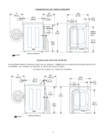
Rough-in Dimensions - installation
 |
UPC - 012505375521
View all Frigidaire FTF530FS manuals
Add to My Manuals
Save this manual to your list of manuals |
Page 3 highlights
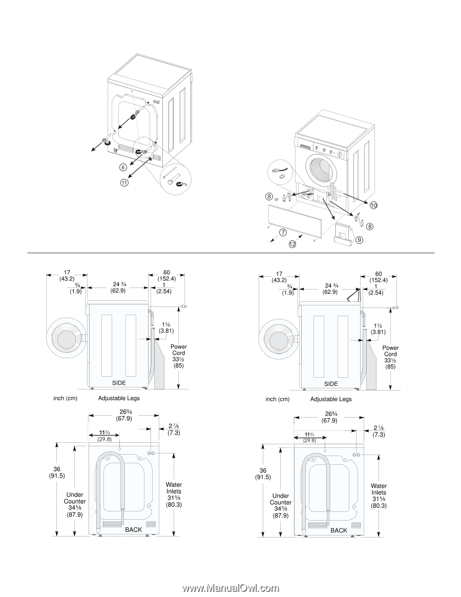
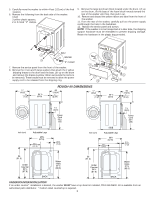
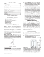
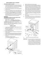
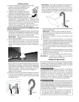
5. Carefully move the washer to within 4 feet (122cm) of the final location. 6. Remove the following from the back side of the washer: 3 bolt 3 yellow plastic spacers, 2 or 3 metal "P" clamps. 9. Remove the large styrofoam block located under the drum. Lift up on the drum, tilt the base of the foam block inwards toward the rear of the washer until free, then pull it out. 10. Remove and discard the yellow ribbon and label from the front of the washer. 11. From the rear of the washer, carefully pull out the power supply cordthrough the hole in the backsheet. 12. Replace the service panel and screws. NOTE: If the washer is to be transported at a later date, the shipping support hardware must be reinstalled to prevent shipping damage. Retain the hardware in the plastic bag provided. BOLT SPACER "P" CLAMP 7. Remove the service panel from the front of the washer. 8. Remove the 4 nuts and 6 large washers that attach the 2 yellow shipping braces to the drum and the base. Lift up on the drum and remove the braces (a yellow ribbon surrounds the items to be removed). These braces must be removed to allow the power ` supply cord to be released from the shipping ring. ROUGH-IN DIMENSIONS UNDER COUNTER INSTALLATION If an under counter* installation is desired, the washer MUST have a top sheet kit installed, P/N 131445600. Kit is available from an authorized parts distributor. *Custom sized countertop is required. 3
-
 1
1 -
 2
2 -
 3
3 -
 4
4 -
 5
5 -
 6
6 -
 7
7 -
 8
8
 |
 |