Frigidaire GLEQ2152ES Installation Instructions - Page 3
Exhaust System Requirements - installation
 |
UPC - 012505374036
View all Frigidaire GLEQ2152ES manuals
Add to My Manuals
Save this manual to your list of manuals |
Page 3 highlights
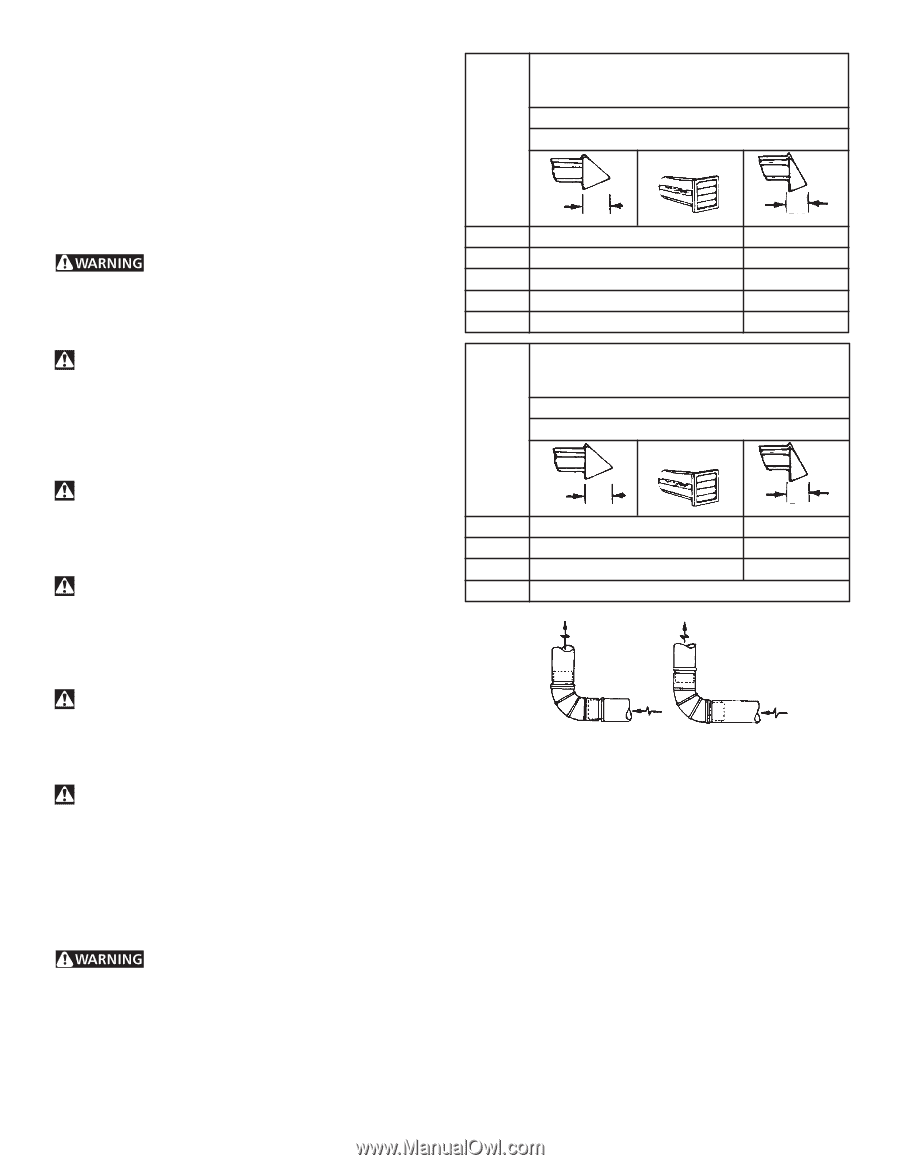
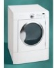
EXHAUST SYSTEM REQUIREMENTS Use only 4 inch (10.2 cm) diameter (minimum) rigid or flexible metal duct and approved vent hood which has a swing-out damper(s) that open when the dryer is in operation. When the dryer stops, the dampers automatically close to prevent drafts and the entrance of insects and rodents. To avoid restricting the outlet, maintain a minimum of 12 inches (30.5 cm) clearance between the vent hood and the ground or any other obstruction. The following are specific requirements for proper and safe operation of your dryer. Failure to follow these instructions can create excessive drying times and fire hazards. Number of 90° Turns 0 1 2 3 4 MAXIMUM LENGTH of 4" (10.2 cm) Dia. Rigid Metal Duct VENT HOOD TYPE (Preferred) Louvered 4" (10.2 cm) 60 ft. (18.28 m) 52 ft. (15.84 m) 44 ft. (13.41 m) 32 ft. (9.75 m) 28 ft. (8.53 m) 2½" (6.35 cm) 48 ft.(14.63 m) 40 ft.(12.19 m) 32 ft. (9.75 m) 24 ft. (7.31 m) 16 ft. (4.87 m) Do not use plastic flexible duct to exhaust the dryer. Excessive lint can build up inside exhaust system and create a fire hazard and restrict air flow. Restricted air flow will increase dryer times. If your present system is made up of plastic duct or metal foil duct, replace it with a rigid or flexible metal duct. Ensure the present duct is free of any lint prior to installing dryer duct. If the dryer is not exhausted outdoors, some fine lint will be expelled into the laundry area. An accumulation of lint in any area of the home can create a health and fire hazard. The dryer exhaust system MUST be exhausted to the outside of the dwelling! Do not allow combustible materials (for example: clothing, draperies/curtains, paper) to come in contact with exhaust system. The dryer MUST NOT be exhausted into a chimney, a wall, a ceiling, or any concealed space of a building which can accumulate lint, resulting in a fire hazard. Exceeding the length of duct pipe or number of elbows allowed in the "MAXIMUM LENGTH" charts can cause an accumulation of lint in the exhaust system. Plugging the system could create a fire hazard, as well as increase drying times. Do not screen the exhaust ends of the vent system, nor use any screws or rivets to assemble the exhaust system. Lint can become caught in the screen, on the screws or rivets, clogging the duct work and creating a fire hazard as well as increasing drying times. Use an approved vent hood to terminate the duct outdoors, and seal all joints with duct tape. All male duct pipe fittings MUST be installed downstream with the flow of air. Explosion hazard. Do not install the dryer where gasoline or other flammables are kept or stored. If the dryer is installed in a garage, it must be a minimum of 18 inches (45.7 cm) above the floor. Failure to do so can result in death, explosion, fire or burns. Number of 90° Turns 0 1 2 3 MAXIMUM LENGTH of 4" (10.2 cm) Dia. Flexible Metal Duct VENT HOOD TYPE (Preferred) Louvered 4" (10.2 cm) 30 ft. (9.14 m) 2½" (6.35 cm) 18 ft. (5.49 m) 22 ft. (6.71 m) 14 ft. (4.27 m) 14 ft. (4.27 m) 10 ft. (3.05 m) NOT RECOMMENDED CORRECT INCORRECT INSTALL MALE FITTINGS IN CORRECT DIRECTION In installations where the exhaust system is not described in the charts, the following method must be used to determine if the exhaust system is acceptable: 1. Connect an inclined or digital manometer between the dryer and the point the exhaust connects to the dryer. 2. Set the dryer timer and temperature to air fluff (cool down) and start the dryer. 3. Read the measurement on the manometer. 4. The system back pressure MUST NOT be higher than 0.75 inches of water column. If the system back pressure is less than 0.75 inches of water column, the system is acceptable. If the manometer reading is higher than 0.75 inches of water column, the system is too restrictive and the installation is unacceptable. 3
-
 1
1 -
 2
2 -
 3
3 -
 4
4 -
 5
5 -
 6
6 -
 7
7 -
 8
8 -
 9
9 -
10
-
11
 |
 |