Frigidaire GRFS2853AF Installation Instructions - Page 1
Frigidaire GRFS2853AF Manual
 |
View all Frigidaire GRFS2853AF manuals
Add to My Manuals
Save this manual to your list of manuals |
Page 1 highlights
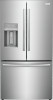
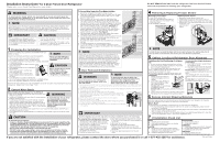
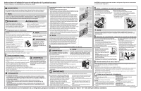
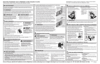
Installation Instructions* for 3 Door French Door Refrigerator *Please refer to your Use & Care Manual for more details. DO NOT REMOVE this label until the refrigerator has been leveled. Please follow all instructions for leveling your refrigerator. WARNING To avoid electric shock, which can cause death or severe personal injury, do not connect your refrigerator to an electrical power source until you have completed Step 2 of these instructions. NOTE If you need to remove the doors to get your refrigerator into the house, please refer to Section 3: "Door Removal/Installation,: or, for more detailed instructions, "Removing Doors" in the Use & Care Manual. These installation instructions are provided only as a possible customer option. Electrolux recommends that you use a service or kitchen contracting professional to install your refrigerator. IMPORTANT If you are installing your refrigerator without connecting it to a water supply, make sure the ice maker(s) are turned off (either via switch or on the display). See the Use & Care Manual for more details. CAUTION • Shifting the refrigerator from side to side may damage flooring. • Do not block the lower front area of your refrigerator. Sufficient air circulation is essential for proper operation. 1 Preparing For Installation NOTE Be sure to coordinate site preparation and installation with your kitchen contractor. Include these minimum guidelines in your site preparation: • Choose a place near a grounded electrical outlet. • Do not use an extension cord or an adapter plug. Please call 1-877-435-3287 if you need assistance with this installation. • Avoid direct sunlight and close proximity to a range, dishwasher or other heat source. • Floor should be level and able to support a fully loaded refrigerator. • Water supply access for your refrigerator's Ice Dispenser. • Plan for easy access to counter tops when removing food. • For complete access to drawers and freezer baskets, doors must be able to fully open. CAUTION Room temperatures below 55°F (13°C) or above 110°F (43°C) will impair cooling ability of your refrigerator's compressor. • Load refrigerator from side of cabinet only. • Do not run retaining straps over handles nor overtighten straps. • Never use refrigerator handles to move the refrigerator. Allow the following clearances for ease of installation, proper air circulation, and plumbing and electrical connections: Sides & Top: 3/8 inch / Rear: 1 inch 2 Connect Water Supply Before Installing The Water Supply Line, You Will Need: • Basic Tools: adjustable wrench, flat-blade screwdriver, and PhillipsTM screwdriver WARNING • • Access to a household cold water line with water pressure between 30 and 100 psi. A water supply line made of ¼ inch (6 mm) OD, copper or braided, flexible, stainless steel tubing. To determine the length of tubing needed, measure the distance from the ice maker inlet valve at the back of the refrigerator to your cold water pipe. Then add approximately 7 feet, so the refrigerator can be moved out for cleaning. To avoid electric shock, which can cause death or severe personal injury, disconnect the refrigerator from electrical power before connecting a water supply line to the refrigerator. • A shutoff valve to connect the water supply line to your household water system. DO NOT use a self-piercing type shutoff valve. • A compression nut and ferrule (sleeve) for connecting a copper water supply line to the ice maker inlet valve. CAUTION To Avoid Property Damage: • Copper or Stainless Steel braided tubing is recommended for the water supply line. Wa- ter supply tubing made of ¼ inch (6 mm) plastic is not recommended to be used. Plastic tubing greatly increases the potential for water leaks, and the manufacturer will not be responsible for any damage if plastic tubing is used for the supply line. • Do not reuse compression fitting or reuse thread seal tape. • DO NOT install water supply tubing in areas where temperatures fall below freezing. • Chemicals from a malfunctioning softener can damage the ice maker. If the ice maker is connected to soft water, ensure that the softener is maintained and working properly. To Connect Water Supply Line To Ice Maker Inlet Valve 1. Disconnect refrigerator from electric power source. 2. Place end of water supply line into sink or bucket. Turn ON water supply and flush supply line until water is clear. Turn OFF water supply at shutoff valve. Steel Clamp Brass Compression Nut Ferrule (Sleeve) 3. Remove plastic cap from water valve inlet and discard cap. Copper 4. If you use copper tubing - Slide brass nut, then ferrule (sleeve) Water line onto water supply line. Push water supply line into water valve inlet as far as it will go (¼ inch). Slide ferrule (sleeve) into valve inlet and finger tighten compression nut onto valve. Tighten another Water Valve Bracket Valve Inlet half turn with a wrench; DO NOT overtighten. See Figure 1. Water Valve If you use braided, flexible stainless steel tubing - The nut is Copper waterline already assembled on the tubing. Slide nut onto valve inlet and finger tighten nut onto valve. Tighten another half turn with a wrench; DO NOT overtighten. See Figure 2. from household water supply (Include enough tubing in loop to allow moving refrigerator out 5. With steel clamp and screw, secure water supply line (copper for cleaning) tubing only) to rear panel of refrigerator as shown. 6. Coil excess water supply line (copper tubing only), about 2½ turns, Steel Clamp behind refrigerator as shown and arrange coils so they do not vibrate or wear against any other surface. 7. Turn ON water supply at shutoff valve and tighten any connections (Include enough tubing that leak. 8. Reconnect refrigerator to electrical power source. 9. To turn ice maker(s) on, ensure Ice Maker is enable on display in loop to allow moving refrigerator out for cleaning) (LED is lit) or set the ice maker's On/Off switch to the "ON" position Braided Flexible Stainless Steel Water Line Valve Inlet (freezer ice maker). Water Valve NOTE Check with your local building authority for recommendations on water lines and associated materials prior to installing your new refrigerator. Depending on your local/state building codes, Electrolux recommends for homes with existing valves its Smart Choice® water line kit 5305513409 with a 6 ft. (1.8 meters) Stainless Steel Water Line and for homes without an existing valve, Electrolux recommends its Smart Choice® water line kit 5305510264 with a 20 ft. (6 meters) Copper Water Line with self-tapping saddle valve. Please refer to www.electroluxappliances.com for more information. 6 ft. (1.8 Meters) Braided flexible stainless steel water line from household water supply. 3 Door Removal/Installation Removing the Doors: WARNING Turn off power to your refrigerator by unplugging the power cord from the wall outlet. NOTE To avoid electric shock, which can cause death or severe personal injury, disconnect the refrigerator from electrical power before connecting a water supply line to the refrigerator. 1. Remove the three screws at the top left and right of the cabinet from both hinge covers, taking care not to damage the door sensor. 2. Disconnect any harnesses between the cabinet and doors by firmly grasping both sides of the connector, then press the latch and pull apart. 3. Trace lightly around the top hinges of the door with a pencil. 4. Remove bulkhead cover at rear of unit to access water tubing. Disconnect water tube from yellow water line at the push-lock connection on rear of unit Pin Mechanism below the bulkhead. 5. Pull the water tube out of the conduit from the top of the cabinet 6. Open both doors to a 90° angle Bottom Hinge Opening 7. Open door to a 90 degree angle then lift off the bottom hinge and set aside 8. Lift doors off bottom hinges and set aside. 9. Unscrew the three bottom hinge screws and remove the hinges on both sides of the cabinet IMPORTANT Open the refrigerator doors to a 90° angle before removing or installing the doors on the lower hinges. To reinstall the refrigerator doors: 1.Replace three bottom hinge screws and hinges on both sides of the cabinet. Ensure screws are tightly snug to hinges on both sides of the cabinet before re-installing doors. 2.Hold the door at a 90˚angle and drop the pin down into the center hinge opening. Rotate slightly in either direction until the door falls fully seated onto the hinge. 3.Reinstall top hinges and screws. 4.Insert and feed water line back into the conduit at the top left door hinge until tube re-appears at rear of unit. 5.Reconnect all harnesses 6.Replace top hinge covers and screws 7.Replace water line bulkhead cover and then reconnect water line to push-lock connection at rear of unit 8.Reconnect electrical power cord to the wall outlet. 4 Removing & Replacing Freezer Drawer Removing Freezer Drawer: 1. Open freezer drawer fully. 2. Remove 4 hex head drawer screws (2 per side) that secure the drawer to the slide assemblies. 3. Lift up drawer to remove. Remove Hex Head Drawer Screw Replacing Freezer Drawer: 1. Extend the Freezer slides from the unit 2. Carefully align support pin with hooks on end of freezer slides and then lower freezer door onto slides 3. Replace the 4 hex head screws that secure the slides to the door (2 on each side) and tighten. NOTE To locate the pin, look inside the drawer and the pin is next to the door liner and the slides. Not all parts are shown in the illustration. Refer to your Use & Care Manual for more details. 5 Cabinet Leveling & Refrigerator Door Alignment Guidelines for Final Positioning of refrigerator: • All four corners of cabinet must rest firmly on floor. • The front should be slightly elevated (to ensure that doors close and seal properly.) • Doors should align with each other and be level. Most of these conditions can be met by raising or lowering the adjustable front rollers. To level the cabinet using the front rollers (if necessary): 1. Slightly open freezer drawer to reveal anti-tip legs at bottom of cabinet. 2. Lower anti-tip legs until they are both touching the floor. Use a pair of pliers to adjust. To raise unit: turn leg clockwise if looking from the top Anti-Tip Legs To lower unit: turn leg counter-clockwise if looking from the top. 3. Ensure both doors are bind-free with their seals touching the cabinet on all four sides and that cabinet is stable. To make final door height adjustments (if necessary): 1. Open freezer drawer to access hinges for refrigerator doors. 2. Insert 6mm Allen wrench into the shaft of the lower hinge. (Included with unit). To lower door: turn adjustment screw counter-clockwise if looking at the door from below.* *Units are shipped with doors in lowest position; initially doors can only be adjusted up. To raise door: turn adjustment screw clockwise if looking at the door from below. Door Raise 6 Remove Internal Shipping Materials Electrolux uses packing foam and tape to secure the internal parts of your refrigerator for shipping. Once the refrigerator is in position, you can remove this material. What's Next? Congratulations! You are ready to begin enjoying your new Electrolux refrigerator. • For important safety instructions and to learn how to operate your refrigerator, please read the entire Use & Care Manual. • You may want to start with the "Normal Operating Sights & Sounds" section of the Manual to learn what to expect during typical operation. • Please register your product. You can register online at www.electroluxappliances.com, scan the code on the Registration Card, or send in the Registration Card. 7 Installation Check List Doors Handles are secure and tight Door seals completely to cabinet on all sides Refrigerator doors are level Leveling Refrigerator is level side-to-side and slightly elevated in front to assist with door and drawer closing (front should be higher than back) Cabinet is sitting solid on all corners Electrical Power House power turned on Refrigerator plugged in Ice Maker(s) House water supply connected to refrigerator No water leaks present at all connections Ice Maker(s) is/are turned ON. Final Checks Shipping material removed Refrigerator and Freezer temperatures set If you are not satisfied with the installation of your refrigerator, please contact the store where you purchased it or call 1-877-435-3287 for assistance. P/N: A22782801
-
 1
1 -
 2
2 -
 3
3
 |
 |