Fujitsu MHU2100AT Manual/User Guide - Page 10
Cable connector specifications, Device connection - interface
 |
UPC - 000052622700
View all Fujitsu MHU2100AT manuals
Add to My Manuals
Save this manual to your list of manuals |
Page 10 highlights
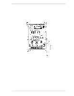
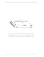
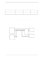
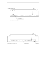
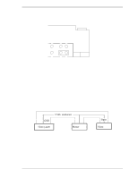
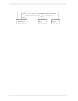
Installation Conditions 3.3.2 Cable connector specifications Table 3.2 lists the recommended specifications for the cable connectors. Table 3.2 Cable connector specifications ATA interface and power supply cable (44-pin type) Name Cable socket (44-pin type) Model 89361-144 Manufacturer FCI IMPORTANT For the host interface cable, use a ribbon cable. A twisted cable or a cable with wires that have become separated from the ribbon may cause crosstalk between signal lines. This is because the interface is designed for ribbon cables and not for cables carrying differential signals. 3.3.3 Device connection Figure 3.9 shows how to connect the devices. Host system ATA-cable Disk Drive #0 ATA-cable DC Power supply Power supply cable Disk Drive #1 Figure 3.9 Cable connections 3-10 C141-E202-01EN
-
 1
1 -
2
-
3
-
4
-
 5
5 -
 6
6 -
 7
7 -
 8
8 -
 9
9 -
 10
10 -
 11
11 -
 12
12 -
 13
13 -
 14
14
 |
 |
