Garmin Dual Frequency Installation Instructions - Page 1
Garmin Dual Frequency Manual
 |
View all Garmin Dual Frequency manuals
Add to My Manuals
Save this manual to your list of manuals |
Page 1 highlights
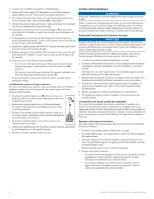
Mounting the Transducer Dual-Frequency Transducer Installation Instructions Warning See the Important Safety and Product Information guide in the Garmin sounder product box for product warnings and other important information. caution Always wear safety goggles, ear protection, and a dust mask when drilling, cutting, or sanding. Follow these instructions to properly install the Garmin 8-pin transom-mount dual-frequency transducer. Tools Needed • Drill and drill bits • 3/8 in. wrench or socket • Masking tape • Number 2 Phillips screwdriver • Marine sealant About the Transducer The transducer is the component of your sonar system that transmits sound waves through the water and receives them to relay the information to your Garmin sounder. With the supplied hardware, you can install the transducer on the transom of your boat. Assembling the Transducer 1. Insert the rubber washer ➊ and the plastic spacer ➋ into the transducer ➌ at the same time. If necessary, moisten the rubber washer to help insert in the transducer along with the plastic spacer. About the Mounting Location The mounting location is the most important consideration when installing a transducer. It is very important to select a mounting location where there will be the least possible turbulent water while the boat is moving. Turbulent water will result in poor sonar performance. When selecting a mounting location, consider the following guidelines: • The location is as close to the center of the boat as possible. • The location is not behind strakes, struts, fittings, water intake or discharge ports, or anything that creates air bubbles or causes the water to become turbulent. • The location is not in the path of the propeller on single-drive boats. The transducer can cause cavitation that can degrade the performance of the boat and damage the propeller. • On boats with outboard or inboard/outboard motors, the location should be at least 15 in. (38 cm) away from the propeller. • On twin-drive boats, the location should be between the drives, if possible. • Avoid locations where the transducer might be jarred when launching, hauling, or storing. Selecting a Transom-Mount Location Before you can select a transom-mount location, you must review the transom-mount location considerations (page 1). 1. Identify a transom-mount location. 2. Drive the boat at the speed you plan to use the sonar. 3. Observe the location you identified in step 1, and verify that the location is relatively free from turbulent water. 4. If the location will subject the transducer to turbulent water, repeat steps 1-3 until you have selected the ideal mounting location. Installing the Transom-Mount Hardware Notice Do not cut the transducer cable. Cutting the transducer cable will void your warranty. 1. Position the transducer mount ➊ at the selected ➏ ➍ mounting location on the transom (page 1). ➍ ➏➎ ➊ ➋ ➐ ➌ 2. Pull the cable back and slide the transducer into the mounting bracket ➍. 3. Place a 5 mm flat washer ➎ on the 10-32 x 1.75 in. screw ➏, and insert the screw through the mounting bracket, transducer, spacer, and rubber washer. 4. Place a 5 mm flat washer on the exposed end of the 10-32 x 1.75 in. screw, and fasten it with the 10-32 lock nut ➐. Do not tighten the 10-32 lock nut. You will adjust the transducer and tighten the nut after you install the transducer on the boat. 2. Align the transducer parallel with the water line ➋, and mark the center location of each hole on the transducer mount. 3. Using a 5/32 in. (4 mm) bit, drill the pilot holes approximately 1 in. (25 mm) deep at the marked locations, while taking the following precautions: ➎➊ ➌ ➋ • To avoid drilling the holes too deep, wrap a piece of tape around the bit at 1 in. (25 mm) from the point of the bit to act as a guide. • If you are installing the bracket on fiberglass, place a piece of tape over the pilot-hole location to reduce cracking of the gel-coat. 4. Apply marine sealant to the included 30 mm M5 screws, and loosely attach the transducer assembly to the transom. 5. Adjust the transducer assembly so that it extends beyond the bottom of the transom ➌ approximately 1/8 in. (3 mm) on fiberglass hulls or 3/8 in. (10 mm) on aluminum hulls. September 2011 190-00789-05 Rev. A Printed in Taiwan
-
 1
1 -
 2
2 -
 3
3 -
 4
4 -
 5
5 -
 6
6 -
 7
7 -
8
-
9
-
10
-
11
-
12
-
13
-
14
-
15
-
16
-
17
-
18
-
19
-
20
 |
 |
