Garmin GCV 10 Scanning Sonar Module Installation Instructions - Page 2
Installation Diagram, Cable Routing Grommets, Blink Codes, Specifications
 |
View all Garmin GCV 10 Scanning Sonar Module manuals
Add to My Manuals
Save this manual to your list of manuals |
Page 2 highlights
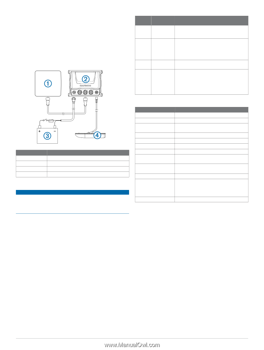
2 Connect the bare-wire end of the power cable to a 12 Vdc power source and to ground. 3 Align the notch on the end of the power cable with the power port on the device, and press the cable into place. 4 Tighten the locking ring. 5 Repeat steps 3 and 4 for the network and transducer cables. Installation Diagram You can use this diagram to identify the connection points from your sounder to the network, power, and transducer. Item À Á Â Ã Description Chartplotter GCV 10 Power Source Transducer Cable Routing Grommets NOTICE Cable routing grommets do not create a waterproof seal. To create a waterproof seal, apply a marine sealant around the grommet and cable after installation. Be sure to test the system before sealing the grommets. When routing cables through your boat, it may be necessary to drill holes to route the connector ends of the cables. A rubber grommet is provided to cover the cable hole for a finished look. You can purchase additional grommets from your Garmin dealer or directly from Garmin at www.garmin.com. Installing the Cable Grommet 1 Mark the location where you want to route the cable. 2 Using a 32 mm (1¼ in. ) paddle drill bit or hole saw, drill the installation hole. 3 Route the cable through the hole to the sounder. 4 Spread the grommet apart at the split, and place it around the cable. 5 Firmly push the grommet into the installation hole until it is seated. 6 Apply marine sealant, as needed, to weatherproof the installation hole. Blink Codes After the sounder is installed, it turns on when the chartplotter is turned on. The two-color (green and red) LED on the sounder indicates its operational status. LED Color Green Red Red/ Green Red State Slow blink Slow blink Slow blink Rapid blink sequence Status The sounder is connected to a chartplotter and is operating properly. You should see sonar data on the chartplotter. The sounder is turned on, but is not connected to a chartplotter, or is waiting to connect to a chartplotter. If the sounder is connected to the chartplotter and this code persists, check the wiring connections. The sounder is in test mode. System error. The chartplotter displays a message indicating the type of failure. When the error condition is fixed, the sounder must be completely disconnected from and reconnected to its power source to clear the error. Specifications Specification Measurement Size (H×W×D) 251 x 192 x 66 mm (9. 9 x 7. 6 x 2. 6 in. ) Weight 845 g (1. 86 lb. ) Case Material Fully gasketed, polycarbonate plastic, water resistant to IEC 60529-IPX7 Temperature Range From -15° to 70°C (from 5° to 158°F) Power Input From 10 to 35 Vdc Power usage 10. 5 W maximum Fuse 4. 0 A, mini 42 Vdc, fast-acting, blade-type Compass Safe Distance 260 mm (10. 2 in. ) Transmit Power (RMS)* 500 W per element (1,500 W combined) *dependent upon transducer rating and depth Frequency 455/800 kHz Depth** 229 m (750 ft) down; 153 m (500 ft) side **maximum depth, dependent upon transducer, water salinity, bottom type, and other water conditions Data Output Garmin Marine Network 2
-
 1
1 -
 2
2 -
 3
3 -
 4
4
 |
 |