Garmin GDL 59 – Data Logger & Wi-Fi Datalink Installation Manual - Page 21
Backshell Assembly and Installation, Final Installation, CAUTION
 |
View all Garmin GDL 59 – Data Logger & Wi-Fi Datalink manuals
Add to My Manuals
Save this manual to your list of manuals |
Page 21 highlights
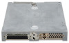
3.5 Backshell Assembly and Installation The GDL 59 connector kit includes a Garmin backshell assembly. Garmin's backshell also gives the installer the ability to easily terminate shield grounds at the backshell housing using the Shield Block method. To assemble the backshell refer to instructions provided in the G1000 System Installation Manual (190-00303-00) and Shield Block Installation Instructions (190-00313-09). 3.6 Final Installation For final installation and assembly, refer to the outline and installation drawings shown in Appendix A of this manual. 1. Assemble the connector backshells as described in Section 3.5. 2. Connect both connectors to the rear plate using the screws provided in the connector kit. 3. Mount the unit rack to the main system rack or other suitable mounting location using the provided nutplates. 4. Assemble the rear plate into the GDL 59 unit rack. 5. Insert the GDL 59 into the rack, noting proper orientation as shown on the installation drawings in Appendix A. CAUTION Do not use excessive force when inserting the GDL 59 into the rack. This may cause damage to occur to the connectors, unit, and/or unit rack. If heavy resistance is felt during installation, stop! Remove the GDL 59 and identify the source of resistance. The rear plate is designed to float in the unit rack. Check to ensure the rear plate is not bound by the connector harness. 6. Lock the GDL 59 in place using the lever-locking handle. Fasten the handle to the GDL 59 body using the provided Phillips screw. CAUTION Start the handle screw into the hole carefully to avoid cross-threading. Do not apply torque in excess of 14 in-lbs to the handle screw. The application of torque exceeding 14 in-lbs to this screw will damage the LRU case and/or retaining hardware. GDL 59 Installation Manual 190-00837-00 Page 3-5 Revision C
-
 1
1 -
2
-
3
-
4
-
5
-
6
-
7
-
8
-
9
-
10
-
11
-
12
-
13
-
14
-
15
-
 16
16 -
 17
17 -
 18
18 -
 19
19 -
 20
20 -
 21
21 -
 22
22 -
 23
23 -
 24
24 -
 25
25 -
 26
26 -
27
-
28
-
29
-
30
-
31
-
32
-
33
 |
 |
