Garmin GHP 10 Marine Autopilot System Installation Instructions - Page 10
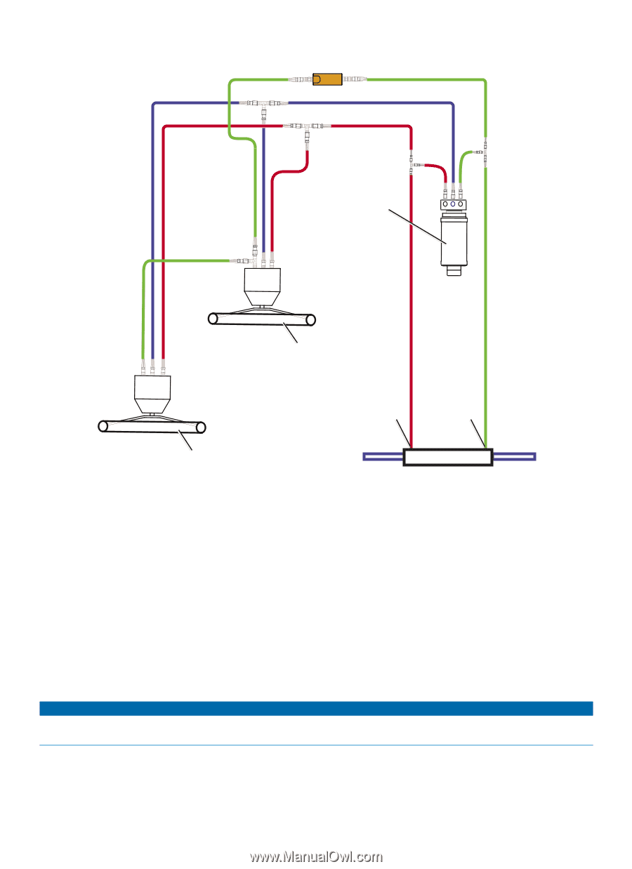
L or 1.2 L Pump Hydraulic Layout on Dual-Helm Boats - mount
 |
View all Garmin GHP 10 Marine Autopilot System manuals
Add to My Manuals
Save this manual to your list of manuals |
Page 10 highlights
2.0 L or 1.2 L Pump Hydraulic Layout on Dual-Helm Boats Shadow Drive Starboard line Return line Port line 2.0 L/1.2 L pump (and motor) SRP SR P Lower helm Port fitting Starboard fitting Upper helm Balanced cylinder Notes: • 2.0 L/1.2 L pump (and motor): ◦ An unbalanced cylinder requires an unbalanced valve on the pump (page 21). ◦ Mount the pump horizontally if possible. Do not mount the pump vertically with the pump end (hydraulic connections) down. • Shadow Drive: ◦ Mount the Shadow Drive horizontally and as level as possible. ◦ Install the Shadow Drive in either the port or the starboard hydraulic steering line. ◦ Always install a length of hose between the helm and the Shadow Drive. ◦ Install the Shadow Drive between the pump and both helms. ◦ Do not install the Shadow Drive directly to the helm. ◦ Do not install the Shadow Drive between the pump and the cylinder. ◦ Do not install the Shadow Drive between the two helms. notice Do not turn the system on until you bleed all the air from the helm, the Shadow Drive, the pump, and all the hydraulic lines. See page 34. 10 GHP 10 Marine Autopilot System Installation Instructions
-
 1
1 -
2
-
3
-
4
-
 5
5 -
 6
6 -
 7
7 -
 8
8 -
 9
9 -
 10
10 -
 11
11 -
 12
12 -
 13
13 -
 14
14 -
 15
15 -
16
-
17
-
18
-
19
-
20
-
21
-
22
-
23
-
24
-
25
-
26
-
27
-
28
-
29
-
30
-
31
-
32
-
33
-
34
-
35
-
36
-
37
-
38
-
39
-
40
-
41
-
42
-
43
-
44
-
45
-
46
-
47
-
48
 |
 |