Garmin GHP 20 Marine Autopilot System for Steer-by-Wire Installation Instructi - Page 8
GHC 10 Installation, Connecting the Devices to a NMEA 2000, Network
 |
View all Garmin GHP 20 Marine Autopilot System for Steer-by-Wire manuals
Add to My Manuals
Save this manual to your list of manuals |
Page 8 highlights
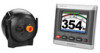
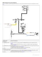
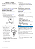
GHC 10 Installation Install the GHC 10 by flush-mounting it in the dashboard near the helm, and connecting it to a NMEA 2000 network. To use advanced features of the GHP 20, optional NMEA 2000-compatible or NMEA 0183-compatible GPS devices, can be connected to the NMEA 2000 network or connected to the GHC 10 through NMEA 0183. Mounting the GHC 10 Notice The temperature range for the GHC 10 is from 5°F to 158°F (from -15°C to 70°C). Extended exposure to temperatures outside of this range (in storage or operating conditions) may cause failure of the LCD screen or other components. This type of failure and related consequences are not covered by the manufacturer's limited warranty. If you are mounting the GHC 10 in fiberglass, when drilling the four pilot holes, it is recommended to use a countersink bit to drill a clearance counterbore through only the top gel-coat layer. This will help to avoid any cracking in the gel-coat layer when the screws are tightened. Stainless-steel screws may bind when screwed into fiberglass and overtightened. Garmin recommends applying an anti-galling, stainless anti-seize lubricant to the screws before installing them. Before you can mount the GHC 10, you must select a mounting location (page 5). 1. Trim the flush-mount template and ensure it will fit in the location where you plan to mount the GHC 10. The flush-mount template is included in the product box, not in these instructions. The flush-mount template has adhesive on the back. 2. Remove the protective liner from the adhesive on the back of the template and apply it to the location where you plan to mount the GHC 10. 3. If you will be cutting the hole with a jigsaw instead of a 317/32 in. (90 mm) hole saw, use a 3/8 in. (10 mm) drill bit to drill a pilot hole as indicated on the template to begin cutting the mounting surface. 4. Using the jigsaw or the 3.5 in. (90 mm) hole saw, cut the mounting surface along the inside of the dashed line indicated on the flushmount template. 5. If necessary, use a file and sandpaper to refine the size of the hole. 6. Place the GHC 10 into the cutout to confirm that the four mounting holes are correct. 7. Select an option: • If the mounting holes are correct, proceed to step 8. • If the mounting holes are not correct, mark the correct locations of the four mounting holes. 8. Remove the GHC 10 from the cutout. 9. Drill the four 1/8 in. (3.2 mm) pilot holes. If you are mounting the GHC 10 in fiberglass, use a countersink bit as advised in the Notice. 10. Remove the remainder of the template. 11. Place the GHC 10 into the cutout. 12. Securely fasten the GHC 10 to the mounting surface using the supplied screws. If you are mounting the GHC 10 in fiberglass, use a anti-galling lubricant as advised in the Notice. 13. Snap the mounting covers ➊ into place. 8 ➊ Connecting the GHC 10 Connect the GHC 10 to the NMEA 2000 network using the included NMEA 2000 drop cable (page 8). Multiple GHC 10 Considerations You can install multiple GHC 10 devices (sold separately) to control the autopilot from different locations on the boat. • All additional GHC 10 devices must be at software version 4.0 or later. • All additional GHC 10 devices must be connected to the NMEA 2000 network (page 8). Connecting the Devices to a NMEA 2000 Network Notice If you have an existing NMEA 2000 network on your boat, it should already be connected to power. Do not connect the included NMEA 2000 power cable to an existing NMEA 2000 network, because only one power source should be connected to a NMEA 2000 network. You can connect the GHC 10 to the CCU through an existing NMEA 2000 network. If you do not have an existing NMEA 2000 network on your boat, all the parts needed to build one are supplied in the GHP 20 package (page 10). To use advanced features of the GHP 20, an optional NMEA 2000-compatible GPS device can be connected to the NMEA 2000 network. For more information on NMEA 2000, go to www.garmin.com. GHP 20 Installation Instructions
-
 1
1 -
2
-
 3
3 -
 4
4 -
 5
5 -
 6
6 -
 7
7 -
 8
8 -
 9
9 -
 10
10 -
 11
11 -
 12
12 -
 13
13 -
14
-
15
-
16
-
17
-
18
-
19
-
20
 |
 |
