Garmin GHP Compact Reactor Hydraulic Autopilot Starter Pack Installation Instr - Page 9
Configuration, Appendix
 |
View all Garmin GHP Compact Reactor Hydraulic Autopilot Starter Pack manuals
Add to My Manuals
Save this manual to your list of manuals |
Page 9 highlights
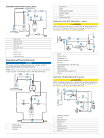
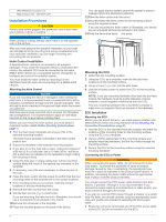
1 Connect the three T-connectors together side-by-side. À 2 Connect the included NMEA 2000 power cable to a 9 to Á 12 Vdc power source through a switch .  à You should connect the power cable to the ignition switch of the boat if possible, or route it through an inline switch (not included). NOTE: The braided drain wire (bare) on the NMEA 2000 power cable must be connected to the same ground as the black wire on the NMEA 2000 power cable. 3 Connect the NMEA 2000 power cable to one of the Tconnectors. 4 Connect one of the included NMEA 2000 drop cables to Ä one of the T-connectors and to the helm control (optional) or to a compatible Garmin chartplotter . Å 5 Connect the other included NMEA 2000 drop cable to the other T-connector and to the CCU . Æ 6 Connect the male and female terminators to each end of Ç the combined T-connectors. Connecting the Autopilot Components to an Existing NMEA 2000 Network A dedicated helm control is not included in all autopilot packages. If you install the autopilot without a dedicated helm control, the autopilot CCU must be connected to the same NMEA 2000 network as a compatible Garmin chartplotter to configure and control the autopilot system. 1 Determine where to connect the CCU and the helm control À (optional) to your existing NMEA 2000 backbone . Á  2 In the location where you plan to connect the CCU, disconnect one side of a NMEA 2000 T-connector from the à network. 3 If necessary, connect a NMEA 2000 backbone extension cable (not included) to the side of the disconnected Tconnector to extend the NMEA 2000 network backbone. 4 Add an included T‑connector for the CCU to the NMEA 2000 backbone by connecting it to the side of the disconnected T‑connector or backbone extension cable. 5 Route the included drop cable to the CCU and to the Ä bottom of the T-connector added in step 4. If the included drop cable is not long enough, you can use a drop cable up to 6 m (20 ft.) long (not included). 6 Connect the drop cable to the CCU and the T-connector. 7 If needed, repeat steps 2 through 6 for the helm control (optional) or a compatible Garmin chartplotter. Connecting Optional NMEA 2000 Devices to the Autopilot System You can use advanced features of the autopilot system by connecting optional NMEA 2000 compatible devices, such as a wind sensor, a water-speed sensor, or a GPS device to the NMEA 2000 network. NOTE: You can connect optional devices that are not NMEA 2000 compatible to the helm control through NMEA 0183 (NMEA 0183 Connection Considerations, page 9). 1 Add an additional T-connector (not included) to the NMEA 2000 network. 2 Connect the optional NMEA 2000 device to the T-connector by following the instructions provided with the device. Configuration The autopilot must be configured and tuned to your boat dynamics. You can use the Dockside Wizard and the Sea Trial Wizard on the helm control or a compatible Garmin chartplotter to configure the autopilot. See the included configuration guide for more information on configuring the autopilot. Appendix NMEA 0183 Connection Diagrams The helm control is not included in all autopilot packages. A helm control must be installed in your autopilot system to connect NMEA 0183 devices according to these diagrams. If you install the autopilot without a helm control, all NMEA devices you plan to use with the autopilot system must be connected to a compatible Garmin chartplotter on the same NMEA 2000 network as the CCU. See the installation instructions provided with your chartplotter for NMEA 0183 connection information. These wiring diagrams are examples of different situations you may encounter when connecting your NMEA 0183 device to the helm control. NMEA 0183 Connection Considerations • See the installation instructions for the NMEA 0183 device to identify the transmit (Tx) A (+) and B (-) wires and receive (Rx) A (+) and B (-) wires. • Each internal Rx and Tx port has 2 wires, labeled A (+) and B (-) according to the NMEA 0183 convention. The corresponding A (+) and B (-) wires of each internal port should be connected to the A (+) and B (-) wires of the NMEA 0183 device. See the table and wiring diagrams when connecting the data cable to NMEA 0183 devices. • You must use 28 AWG, shielded, twisted-pair wiring for extended runs of wire. Solder all connections and seal them with heat-shrink tubing. • See Specifications, page 11 for a list of the approved NMEA 0183 sentences that are output by and input to your device. 9
-
 1
1 -
2
-
3
-
 4
4 -
 5
5 -
 6
6 -
 7
7 -
 8
8 -
 9
9 -
 10
10 -
 11
11 -
 12
12
 |
 |
