Garmin GHP Compact Reactor Hydraulic Autopilot Installation Instructions - Page 2
Autopilot Switch Mounting and Connection Considerations
 |
View all Garmin GHP Compact Reactor Hydraulic Autopilot manuals
Add to My Manuals
Save this manual to your list of manuals |
Page 2 highlights
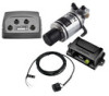
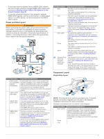
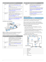
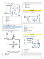
• To avoid interference with a magnetic compass, the device should not be installed closer to a compass than the compass-safe distance value listed in the product specifications. • The area behind the mounting surface must allow room for routing and connecting the cables. Helm Control Connection Considerations A dedicated helm control is not included in all autopilot packages. If you install the autopilot without a dedicated helm control, the autopilot CCU must be connected to the same NMEA 2000 network as a compatible Garmin chartplotter to configure and control the autopilot system. • The helm control must connect to the NMEA 2000 network. • Optional NMEA® 0183 devices, such as wind sensors, water- speed sensors, or GPS devices can be connected to the helm control using a NMEA data cable (NMEA 0183 Connection Considerations, page 9). CCU Mounting and Connection Considerations • The CCU is the primary sensor of the GHP Compact Reactor Hydraulic autopilot system. For best performance, observe these considerations when selecting a mounting location. ◦ A handheld compass should be used to test for magnetic interference in the area where the CCU is to be mounted. If the needle on a handheld compass moves when you hold it where you intend to mount the CCU, magnetic interference is present. You must choose another location and test again. ◦ The CCU should be mounted on a rigid surface for best performance. • Mounting screws are provided with the CCU. If you use mounting hardware other than the provided screws, the hardware must be quality stainless or brass material to avoid magnetic interference with the CCU. Test any mounting hardware with a handheld compass to make sure no magnetic fields are present in the hardware. Finding the Best Mounting Location 1 Create a list of all suitable mounting locations for the CCU where no iron, magnets, or high-current wires are located within 60 cm (2 ft.). A large magnet, such as a subwoofer-speaker magnet should be no closer than 1.5 m (5 ft.) to these locations. 2 Locate the center of rotation of the boat, and measure the distance between the center of rotation and each of the suitable mounting locations you listed in step 1. 3 Select the location closest to the center of rotation. If more than one location is approximately the same distance from the center of rotation, you should select the location that best meets these considerations. • The best location is closest to the centerline of the boat. • The best location is lower in the boat. • The best location is slightly forward in the boat. ECU Mounting and Connection Considerations • The ECU can be mounted on a flat surface, facing any direction. • Mounting screws are included with the ECU, but you may need to provide different screws if the supplied screws are not suitable for the mounting surface. • The ECU must be mounted within 0.5 m (19 in.) of the pump. ◦ The cables connecting the ECU to the pump cannot be extended. • The ECU must be mounted in a location where it will not be submerged or exposed to wash down. • The ECU power cable connects to the boat battery, and it can be extended if needed (Power Cable Extensions, page 7). Pump Mounting Considerations Consult the hydraulic-layout diagrams in these instructions to help determine the pump-installation location (Hydraulic Layouts, page 4). • The pump must be mounted at a location to which you can extend the hydraulic steering lines of the boat. • The pump should be mounted horizontally if possible. • If the pump must be mounted vertically, with the hydraulic connections facing upward. Shadow Drive Mounting Considerations NOTE: The Shadow Drive is a sensor you install in the hydraulic steering lines of your boat. It detects when you manually take control of the helm and suspends autopilot control of the boat. NOTE: If your autopilot package does not include a Shadow Drive, you should install a manual switch to disable the autopilot if needed. • The Shadow Drive must be mounted horizontally and as level as possible, with cable ties firmly securing it in place. • The Shadow Drive must be mounted at least 305 mm (12 in.) away from magnetic materials or devices, such as speakers or electric motors. • The Shadow Drive should be mounted closer to the helm than to the pump. • The Shadow Drive should be mounted lower than the helm, but higher than the pump. • The Shadow Drive must not be connected directly to the fitting at the back of the helm. There must be a length of hose between the fitting at the helm and the Shadow Drive. • The Shadow Drive must not be connected directly to a hydraulic T-connector in the hydraulic line. There must be a length of hose between a T-connector and the Shadow Drive. • In a single-helm installation, there must not be a T-connector between the helm and the Shadow Drive. • In a dual-helm installation, the Shadow Drive should be installed between the pump and the hydraulic T-connector that leads to the upper and lower helm, closer to the helm than to the T-connector. • The Shadow Drive must be installed in either the starboard steering line or the port steering line. The Shadow Drive must not be installed in either the return line or the high-pressure line, if applicable. Autopilot Switch Mounting and Connection Considerations If your autopilot package does not include a Shadow Drive valve, you should install a manual Single Pole Single Throw (SPST) switch (not included) to disable the autopilot if necessary. The switch should be installed near the primary helm, so it is easily accessible when operating the boat. The switch should be connected to the same wires that connect a Shadow Drive valve. If needed, the wires can be extended with 28 AWG (0.08 mm2) wire. Alarm Mounting and Connection Considerations • The alarm should be mounted near the primary helm station. • The alarm can be mounted under the dashboard. • If needed, the alarm wires can be extended with 28 AWG (0.08 mm2) wire. NMEA 2000 Connection Considerations • The CCU and the helm control must connect to a NMEA 2000 network. 2
-
 1
1 -
 2
2 -
 3
3 -
 4
4 -
 5
5 -
 6
6 -
 7
7 -
 8
8 -
9
-
10
-
11
-
12
 |
 |
